Injection-Molded Part Design Checklist Before Tooling
Review material, wall thickness, draft, ribs, bosses, undercuts and the practical tooling decisions that connect a plastic part to reliable molding and assembly.
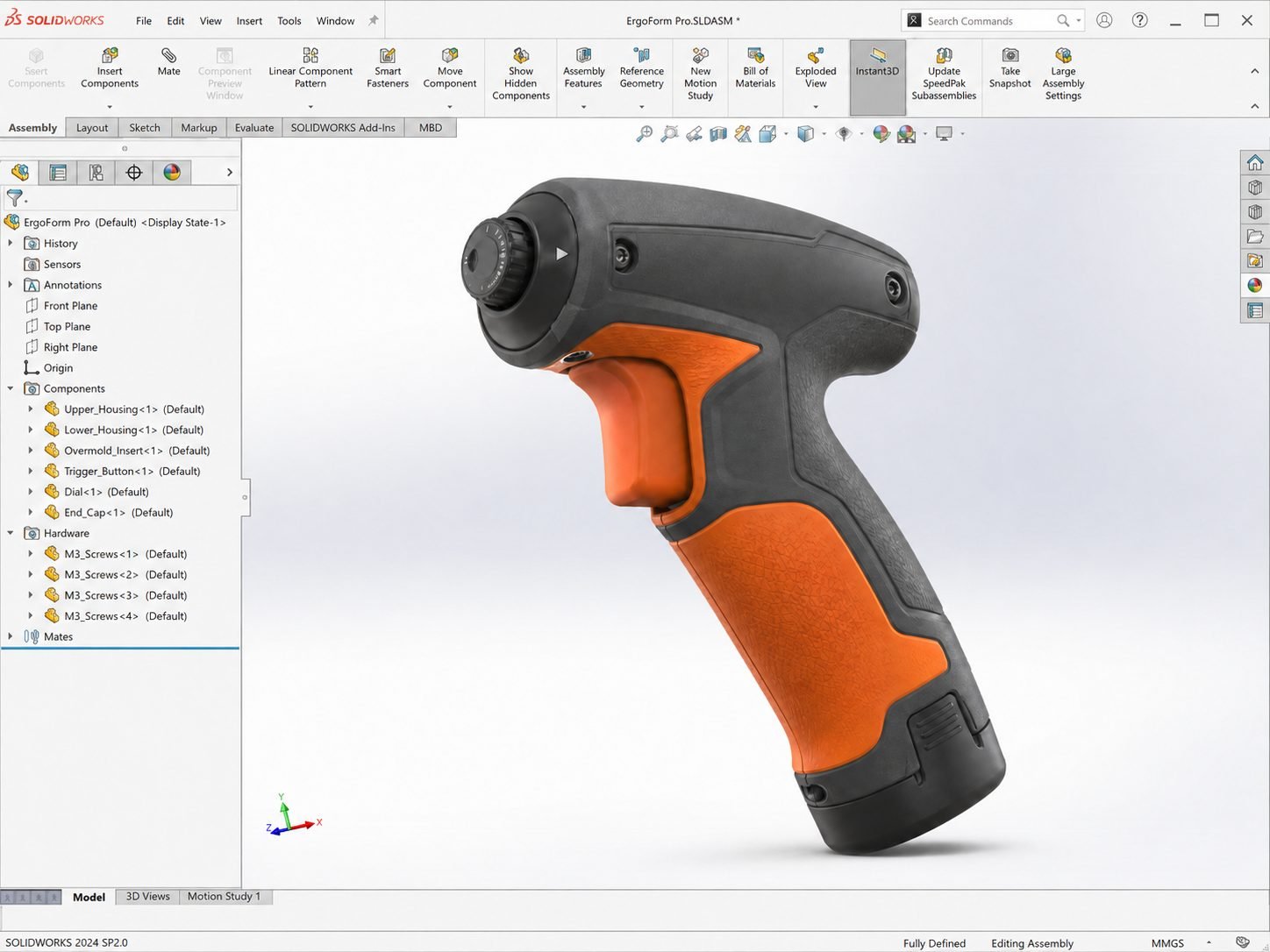
Injection molding can produce highly repeatable plastic parts at scale, but a design change becomes harder to accommodate once the mold has been designed or manufactured. A small feature in CAD can affect how the tool opens, where the plastic flows or whether the part releases without damage.
A DFM review before tooling checks molding, filling, cooling, ejection, warpage, appearance and assembly together. The aim is to resolve avoidable geometry and specification problems while changes are still practical, and give the toolmaker a clear basis for quotation and mold design.
Material, geometry, tooling, process and production requirements interact. A checklist helps expose decisions and open questions; it does not certify a part or replace the mold designer's review.
What Does “Tooling-Ready” Mean for an Injection-Molded Part?
A tooling-ready part has a controlled design definition and a credible manufacturing approach. Material, mold architecture, parting, draft and ejection have been considered alongside functional dimensions, appearance, assembly and production needs. Known risks have an owner and a plan for resolution.
Readiness for a preliminary tooling quote is different from approval to cut steel. A quotation can include clearly stated assumptions or alternatives. Final tool design needs agreement on the features and requirements that affect the mold. The mold designer, toolmaker and molder still need to review the design and confirm their proposed approach.
Communicate expected order quantities, annual demand and intended tool life. These influence discussions about cavity count, automation, tooling mechanisms and inspection. A CAD designer cannot guarantee tooling success independently of that engineering input.
1. Confirm the Material and Application
Start with what the part must withstand: loads, impacts, operating temperatures, chemicals, moisture and exposure during use. Resin selection affects stiffness, strength, shrinkage, dimensional stability, surface appearance and how the melt fills the tool. Properties must be evaluated for the actual application, including sustained loading where creep matters.
Specify the intended grade, reinforcement, color and relevant application requirements rather than only naming a polymer family. Different grades within a family can behave differently. If material selection remains open, identify the candidates and make that uncertainty explicit in the tooling request.
Confirm the chosen grade with the material supplier and molder. Document permitted substitutions and their approval route: changing resin after tool design may affect shrinkage assumptions, fit, processing and appearance.
2. Review Overall Part Geometry
Inspect the part in the intended mold-opening direction and in assembly. Identify unnecessary complexity, deep or difficult cavities, inaccessible features, thin webs, heavy sections and abrupt transitions. Separate functional requirements from features that exist only because of an early modeling choice.
For each difficult feature, ask what tool surface forms it and how that surface withdraws. A recess that is easy to sketch may need a fragile core or additional tool movement. A cosmetic face may constrain both the parting line and gate location.
Use sections through the model to inspect hidden thickness changes and intersections. Review radii and transitions for load transfer and moldability without creating extra material concentrations. Changes should support the intended molding process and preserve mating interfaces.
3. Check Wall Thickness
Consistent nominal wall thickness generally helps the part fill and cool more evenly. Large transitions can leave neighboring regions with different cooling and shrinkage behavior. Thick sections may contribute to sink, internal voids or extended cooling, while excessively thin sections can create filling difficulty or inadequate structural performance.
There is no universal wall thickness for a molded part. Appropriate thickness depends on the resin grade, flow length, geometry, tooling and application. Review thin sections along the actual flow path, not only at the model's minimum-thickness point.
Where a region is unnecessarily solid, consider coring it out and supporting the shell with ribs. Where thickness must change, assess a gradual transition and the effect on adjacent surfaces. Protolabs' wall-thickness guidance is a useful reference for these relationships; confirm the design with the selected molder.
4. Review Ribs and Bosses
Ribs can stiffen a wall without making the entire wall thicker. Bosses locate or support screws, inserts and other fastening features. Their benefit depends on the load path, support and assembly forces, not simply on adding more plastic.
Review rib-to-wall relationships at the rib base, where draft and fillets affect local thickness. Multiple ribs converging into a boss can produce a thick intersection even when each individual feature looks reasonable. Such concentrations deserve particular attention behind visible exterior surfaces because of sink risk.
Consider cored bosses, separated support ribs and gussets where appropriate. Check boss bending, fastening loads and access as well as moldability. Size features with reference to the selected resin and fastening system; a single rib or boss thickness ratio cannot settle every design.
5. Add Draft Where the Mold Requires It
Draft is a taper on a surface that allows clearance to develop as the part moves away from the forming tool surface. It helps reduce rubbing, drag marks and resistance during release. Evaluate each face against the direction in which its core, cavity or side action withdraws.
The needed draft depends on material, feature depth, surface texture, finish, ejection strategy and cosmetic requirements. Textured surfaces need particular attention because the texture can resist release; confirm the texture and draft together with the toolmaker.
Check internal walls, ribs, bosses and deep pockets as well as the exterior shell. Adding draft changes dimensions along a feature's depth, so define where a fit or critical dimension applies. Do not assume one angle suits every face or that a zero-draft interface is acceptable without tooling review.
6. Review Parting Line Strategy
The parting line is the boundary where mating mold sections meet on the part. Its location affects tool access, visible witness lines, feature placement and the surfaces used for shutoffs, where tool faces meet to keep plastic out of an opening or separate features.
Explore how alternative parting locations affect appearance and undercuts. Moving a line toward an edge may improve its visibility on one face but complicate a nearby opening or shutoff. Check possible mismatch or flash at interfaces that must fit, seal or remain comfortable to touch.
Mark preferred and restricted areas, then review the proposal with the mold designer. There is not always one correct parting line; the decision balances function, appearance, tool construction and repeatable operation.
7. Identify Undercuts and Side Actions
An undercut is a feature that traps the part relative to the proposed tool-opening or release direction. Examples can include a side opening, internal hook or return lip. Its status depends on the mold architecture: changing the parting strategy can change whether a feature is trapped.
Slides, lifters, removable inserts or other mechanisms may be needed to form and release these features. They introduce movement, access, sequencing or handling considerations that can increase tooling complexity and maintenance needs.
First ask whether the feature can be reoriented, opened through another surface or redesigned while retaining its function. Keep necessary undercuts explicit in the RFQ. Flexible release is only an option when the material, geometry and allowable deformation support it; do not assume a snap feature can simply be pulled off a core.
8. Review Holes, Cores and Openings
Through holes, blind holes and openings need a practical way to be formed. Hole orientation can determine whether a core follows the main opening direction or requires side movement. Check feature accessibility before deciding that an opening is straightforward to mold.
Review core-pin support, blind-hole depth and the plastic remaining between a hole and neighboring walls. Long, slender cores deserve toolmaker review for deflection and durability. Closely spaced features can leave difficult tool sections as well as weak areas in the molded part.
Confirm which holes are intended to be molded and which, if any, require a later operation for functional reasons. Consider how flow divides around cores and rejoins downstream, especially near loaded or visible areas.
9. Check Ejection Strategy
The molded part needs a supported, repeatable way to leave the tool after cooling. Discuss the expected retention side and available areas for ejector pins, sleeves, plates or another suitable ejection arrangement with the mold designer.
Identify areas where ejector marks are acceptable and where they would interfere with appearance, sealing or contact. Ejection forces should act through sufficiently supported regions; pushing on a thin unsupported panel can deform it while it is still warm.
Review ejection together with draft and feature depth. Marking every convenient surface as cosmetically protected can leave the toolmaker without a practical release arrangement. Resolve these competing requirements before the tooling layout is fixed.
10. Review Flow, Gating and Weld-Line Considerations
The gate introduces the melt into the cavity, so its location affects flow paths and the remaining gate mark. Review possible entry areas, long flow paths, thin restrictions and regions where flow splits around an opening and meets again.
Meeting flow fronts can form weld or knit lines that affect appearance and may affect strength. Air can become trapped where filling fronts converge or at difficult-to-vent regions. Flag these concerns near loaded features, sealing areas and visible surfaces for the molder's review.
A visual CAD review cannot predict the complete filling process. Complex or high-risk parts may need dedicated mold-flow analysis using suitable material data and representative tooling and process assumptions. BASF's filling-analysis example illustrates how injection location can affect filling, fiber orientation and warpage. Analysis informs decisions; tool trials still verify the outcome.
11. Check for Sink, Warpage and Cooling Risks
Sink is a local surface depression associated with shrinkage beneath the surface, often near thicker material. Warpage is a change in overall shape resulting from uneven shrinkage and related effects. A flat CAD surface does not establish that the molded surface will stay flat.
Review heavy sections, asymmetric ribs, uneven geometry and thick intersections. Material behavior, including reinforcement orientation where applicable, interacts with filling, packing, cooling conditions and mold design. Cooling access around deep or crowded features also needs tooling input.
Identify where distortion would affect assembly or appearance and decide how it will be evaluated. DFM can reduce avoidable risks, but it does not guarantee that defects disappear. Preserve a plan for sample inspection, process development and any justified adjustments after mold trials.
12. Review Cosmetic and Appearance Requirements
Identify visible surfaces and distinguish them from hidden or less critical areas. Consumer-product housings often need deliberate control of parting lines, gate marks, ejector marks, texture and gloss because these features remain visible after assembly.
Communicate the actual cosmetic acceptance criteria before tooling: designated surface zones, approved texture or finish references, color expectations and relevant viewing conditions. Use agreed samples or project specifications where available instead of an undefined instruction such as “premium finish.”
Review appearance with manufacturing function. Texture affects release, a gate may leave a visible vestige, and a parting line may cross a hand-contact area. Agree acceptable locations and any trimming or finishing operations before the quote and tool design assume a different result.
13. Check Tolerances and Critical Dimensions
Identify dimensions that control fit, alignment, sealing and other functional interfaces. Evaluate mating features as a tolerance stack across the assembly; two individually acceptable parts can still interfere when their variations combine unfavorably.
Realistic molded-part tolerances depend heavily on material, geometry, part size, shrinkage, process and tooling. Features formed within one tool section may behave differently from relationships across the parting line or moving tool elements. Ask the molder to assess capability against the actual critical requirements.
Avoid applying tight limits to every surface. Define inspection references and relevant measurement conditions for critical features, and agree how shrinkage compensation will be handled in tool design. Manufacturing Drawings & GD&T Services can translate functional requirements into clear dimensional controls and inspection intent.
14. Review Assembly and Fastening Features
Check snap fits for assembly deflection, retention and required service cycles in the intended resin. Review screw bosses for fastening loads and the specified fastener. Threaded inserts need suitable surrounding geometry and installation access; heat staking, where appropriate, needs accessible posts and a defined joining process.
Check tool access, assembly sequence, mating clearances and potential interference after molding variation. A boss that molds successfully can still crack during fastening, and a snap that assembles once may not suit repeated opening. Include representative assembly evaluation in the validation plan.
The Ergonomic Handheld Power Tool Housing portfolio describes a housing with an overmolded grip, rotary dial, trigger, PCB mount plate and battery pack. It illustrates the assembly context a housing review must address, without establishing production validation. Product Design Engineer support and Mechanical CAD Services can coordinate these component relationships.
15. Confirm the CAD and Drawing Package
Before tooling quotation or design, issue a consistent package with a clear status. A preliminary quote can use an identified development revision; approval for tool manufacture needs the agreed release definition. Make open questions visible rather than burying them in email history.
- Current 3D model in the supplier's agreed format, with units and part identification.
- Manufacturing drawing with critical dimensions, tolerances and relevant inspection requirements.
- Material grade, finish, cosmetic zones and any approved alternatives.
- Revision information shared across the model, drawing and neutral exports.
- Assembly context, purchased hardware and applicable 2D details.
- Expected quantities, supply scope and unresolved tooling questions.
Not every project requires every item. Agree the contents and which files control requirements. Do not apply guessed shrinkage scaling to the product model; coordinate compensation with the toolmaker and identify any tooling-specific geometry separately.
Use What Should a Manufacturer Ready CAD Package Include? for the overall handoff and Manufacturing Drawing Package Checklist for Supplier RFQs for documentation detail. If native models need revision, SolidWorks Design Services can support coordinated part, assembly and drawing updates.
16. Final Injection-Molding DFM Checklist
Use this as a practical review aid, not a universal acceptance standard. Mark non-applicable items and record unresolved issues with an owner, required evidence and next action. A checked item means it has been reviewed to the level needed for this release stage.
- Material is selected and documented.
- Application requirements are understood.
- Finish and appearance requirements are defined.
- Wall thickness and flow-length implications have been reviewed.
- Thick sections and transitions have been reviewed.
- Ribs, bosses and their intersections have been reviewed.
- Sharp transitions have been minimized where appropriate.
- Draft has been reviewed for each relevant release direction.
- Parting line and shutoffs have been considered.
- Undercuts and any required tooling mechanisms have been identified.
- Holes, cores and openings have been reviewed for tool access.
- Ejection strategy and acceptable mark locations have been considered.
- Gate, flow, weld-line and cooling risks have been reviewed.
- Critical dimensions and mating interfaces are identified.
- Functional tolerances and inspection expectations are defined.
- Cosmetic requirements are documented.
- Assembly and fastening requirements have been reviewed.
- Final CAD revision and issue status are confirmed.
- Drawing revision matches the model and exports.
- Material and relevant manufacturing information are included.
- Expected quantities and production requirements are stated.
- Open questions have owners and a toolmaker review is planned.
Common Injection-Molding Design Mistakes
- Ignoring parting: features are finalized without considering how the mold separates.
- Insufficient draft: release surfaces or texture requirements are considered only after geometry approval.
- Excessive wall thickness: stiffness is added through solid mass without reviewing cooling and sink risk.
- Thick rib and boss intersections: individually reasonable features combine into a heavy material concentration.
- Unplanned undercuts: a hook or opening creates additional tooling movement that the quote did not anticipate.
- Ignoring ejection: no supported release locations remain, or expected ejector marks conflict with cosmetic features.
- Over-tolerancing: tight controls are applied without a functional reason or capability review.
- Unclear appearance requirements: visible surfaces, texture and acceptable marks are left to assumption.
- Outdated CAD: the toolmaker receives geometry that no longer matches drawings or mating components.
- Late DFM: avoidable design questions are raised only after tooling work has started.
The wider DFM Checklist Before Sending a Product to a Manufacturer helps connect this molding review to material, assembly and release decisions across the complete product.
When Should Injection-Molding DFM Happen?
Begin during early design, when material, product architecture and likely parting directions are still flexible. Review again before prototype and tooling decisions: a prototype can answer fit or usability questions without reproducing molded material behavior, surface quality or release conditions.
Before the final tooling quotation, resolve issues that change supplier scope and identify remaining assumptions. Before mold design is finalized, review the proposed parting, gates, ejection, critical dimensions and cosmetic restrictions with the tooling team.
Earlier geometry changes are usually easier and less expensive than modifying a mold after tooling has progressed. Continue reviewing agreed changes through sample evaluation and release; a pre-tooling review is a decision point within development, not the end of validation.
When You Need Injection-Molding Design Support
Focused support is useful when a plastic part looks complete but draft, wall transitions, undercuts, fastening or supplier requirements remain unresolved. Start by identifying the current design stage, intended material, production quantities and the decisions needed before tooling can proceed.
Injection Molding Design Services can help develop and review the part geometry and handoff requirements for discussion with the toolmaker. This can connect to Design for Manufacturing and product design support when the issue extends into assembly or product architecture. A useful next step is a clear list of design actions and supplier questions tied to the current CAD revision.