Mechanical design services

Mechanical design services from concept to production.

Engineering support for manufacturers, hardware startups and product teams that need production-ready CAD, DFM, drawings and validation.

  • Product Design
  • Mechanical CAD
  • DFM
  • Manufacturing Drawings
  • FEA

Talha Javed Malik provides mechanical engineering services for manufacturing companies, engineering and hardware startups, product designers, automation teams, industrial equipment manufacturers, medical device developers and consumer product companies. Start with focused mechanical CAD services, DFM, simulation or engineering documentation, then combine disciplines into a controlled product development scope. These engineering design services can support one defined technical problem, overflow design capacity or a complete mechanical product development program. The work connects requirements, parametric CAD, design reviews, prototype development, manufacturing feedback and production release so each decision is recorded and each deliverable supports the next stage. Review mechanical engineering projects for applied examples or learn more about the mechanical design engineer responsible for the work.

Discuss Project
Core engineering services

Engineering services organized around manufacturing decisions.

Start with the next product or manufacturing decision, then build only the engineering scope it requires.

Each service begins with the decision a customer needs to make: how the product should work, how it will be manufactured, what files suppliers need and what risks should be checked before money is committed to prototypes, machining, tooling or production.

SolidWorks Design Services

  • Parametric SolidWorks CAD
  • Parts and mechanical assemblies
  • Manufacturing drawings
  • BOM creation
  • Revision-controlled handoff
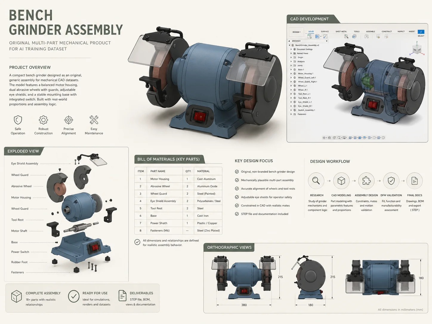
Bench grinder exploded SolidWorks assembly with parts, bill of materials and manufacturing documentation
Engineering evidence from the existing project portfolio
Overview

Parametric SolidWorks design services for parts, mechanical assemblies, mechanisms and production-ready CAD. Models are built with stable references, intentional design features, practical configurations and an assembly structure that remains usable when dimensions or interfaces change.

Work can begin from sketches, marked-up drawings, scans, reference products or incomplete CAD. Typical outputs include native SLDPRT and SLDASM files, STEP and STL exchange files, exploded views, BOM creation and linked SLDDRW drawing files.

The objective is not simply clean geometry; it is SolidWorks CAD that supports design reviews, revision control, supplier quotation, prototype builds and later manufacturing changes without losing design intent.

Deliverables
  • Native SLDPRT parts
  • Native SLDASM assemblies
  • SLDDRW drawing files
  • STEP and STL exports
  • Exploded assembly views
  • Bill of materials
  • Manufacturing drawings
  • Revision support

Typical Applications

  • Industrial products
  • Mechanical equipment
  • Product enclosures
  • Mechanisms and assemblies

Software Used

  • SolidWorks
  • SolidWorks Simulation
  • eDrawings

Manufacturing Outputs

  • Supplier-ready STEP
  • PDF and DWG drawings
  • Flat-pattern DXF
  • BOM and revision package
Revision Process

Source models remain parametric and editable. Review comments, supplier feedback and interface changes are incorporated through controlled milestones so downstream files remain aligned with the approved CAD.

Bench grinder mechanical assembly with exploded view and bill of materials
Related Project

Bench Grinder Assembly

A complete multi-part assembly developed with manufacturing drawings, exploded views, item balloons and a controlled bill of materials.

View Portfolio
Ready to discuss your project?

Start with the engineering problem and the files already available.

Mechanical CAD Services

  • 3D CAD modeling
  • Assembly and mechanism design
  • Tolerance stack-up review
  • Production-ready CAD
  • Supplier documentation
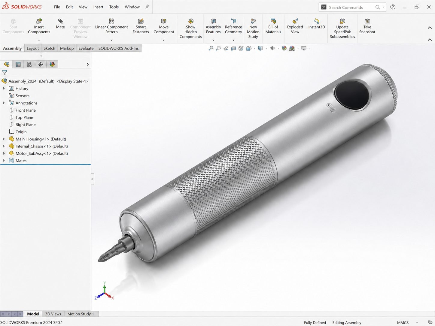
Precision cordless screwdriver mechanical assembly with gearbox, electronics and housing integration
Engineering evidence from the existing project portfolio
Overview

Mechanical CAD services that convert a rough concept, legacy drawing or existing prototype into resolved 3D parts and assemblies. The engineering workflow covers CAD modeling, assembly design, mechanism layout, interface definition, material and process assumptions, tolerance stack-up review and manufacturing documentation.

Models are checked for fit, motion, access, fastening, serviceability and realistic production methods rather than treated as isolated shapes. Support is suitable for industrial products, automation equipment, enclosures, fixtures and electromechanical assemblies.

Deliverables can include production-ready CAD, supplier drawings, BOMs and neutral exchange files for CNC machining, rapid prototyping, sheet metal fabrication or vendor review.

Deliverables
  • Parametric part models
  • Mechanical assemblies
  • Mechanism layouts
  • Tolerance review
  • Interference checks
  • STEP and STL exports
  • Production drawings
  • Revision support

Typical Applications

  • Automation equipment
  • Industrial machinery
  • Fixtures and tooling
  • Electromechanical products

Software Used

  • SolidWorks
  • AutoCAD
  • Fusion 360

Manufacturing Outputs

  • Native editable CAD
  • Supplier STEP files
  • DWG and DXF files
  • PDF drawings and BOM
Revision Process

Interfaces, mates, clearances and design assumptions are reviewed at defined checkpoints. Approved changes are captured in the source CAD before supplier or prototype files are regenerated.

Precision cordless screwdriver product assembly with planetary gearbox and electronics
Related Project

Precision Cordless Screwdriver

An electromechanical product integrating a planetary gearbox, motor, battery, electronics and serviceable housing architecture.

View Portfolio
Ready to discuss your project?

Start with the engineering problem and the files already available.

Product Design Engineering

  • Mechanical product development
  • Internal packaging
  • Prototype design
  • DFM and design reviews
  • Manufacturing handoff
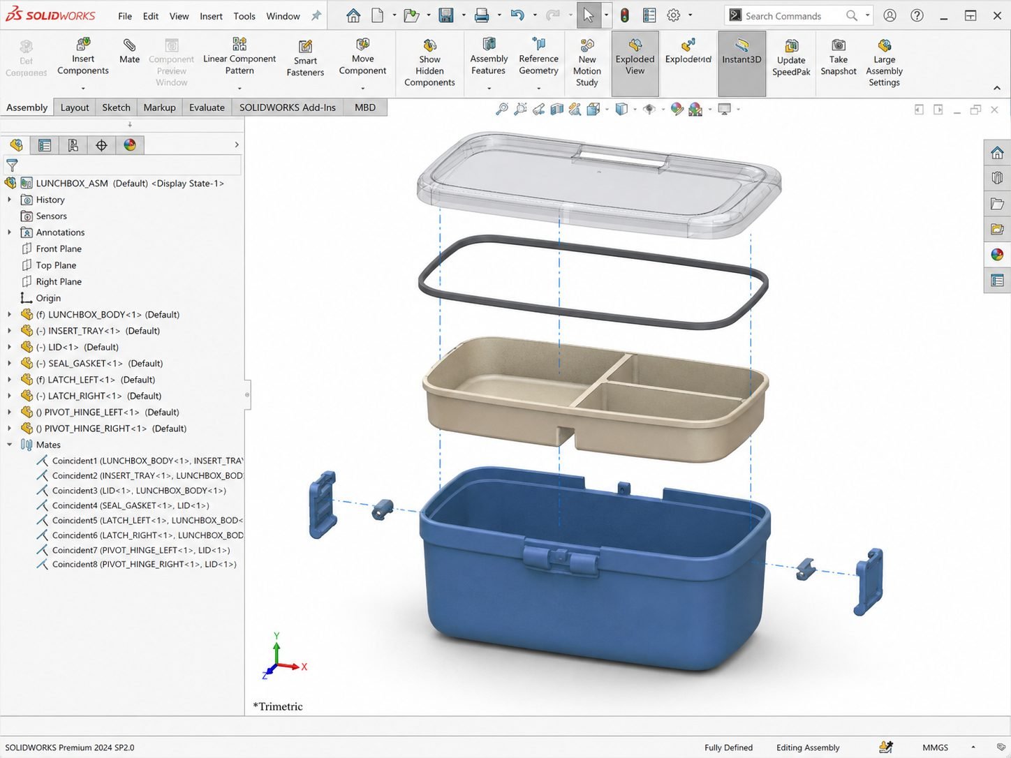
Modular lunchbox product design exploded assembly with seals, latches and internal containers
Engineering evidence from the existing project portfolio
Overview

Mechanical product development from an early idea, reference image or proof-of-concept prototype through resolved architecture, detailed CAD and manufacturing handoff. As a product design engineer, Talha develops internal packaging, user and service interfaces, part separation, fastening, sealing, assembly logic and manufacturing strategy alongside the external form.

Industrial product design decisions are tested against function, available space, materials, production volume and supplier capability. The scope can include prototype design, CAD design services, rapid prototyping files, design reviews, DFM updates and engineering documentation for release.

This creates a traceable path from product requirements to buildable mechanical assemblies for hardware startups and established product teams.

Deliverables
  • Product architecture
  • Concept CAD options
  • Internal component packaging
  • Prototype-ready files
  • Assembly strategy
  • DFM review
  • Production CAD
  • BOM and revisions

Typical Applications

  • Hardware startups
  • Consumer products
  • Medical devices
  • Industrial product teams

Software Used

  • SolidWorks
  • Fusion 360
  • AutoCAD

Manufacturing Outputs

  • Prototype STEP and STL
  • Editable assembly CAD
  • Manufacturing drawings
  • Production handoff package
Revision Process

Concepts progress through review gates for architecture, interfaces, prototype findings and manufacturing feedback. Decisions are recorded so the final handoff reflects the approved product requirements.

Modular lunchbox system exploded SolidWorks assembly
Related Project

Modular Lunchbox System

A multi-container consumer product developed around sealing, stacking, latch access, assembly logic and production-ready part separation.

View Portfolio
Ready to discuss your project?

Start with the engineering problem and the files already available.

Design for Manufacturing and DFM Services

  • Injection molding DFM
  • CNC machining DFM
  • Sheet metal fabrication
  • Tolerance and datum review
  • Supplier feedback resolution
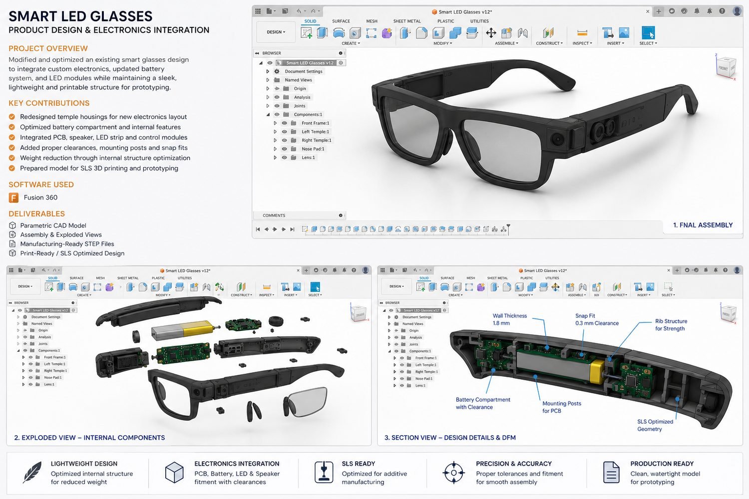
Smart LED glasses product section views showing electronics packaging, ribs and housing details
Engineering evidence from the existing project portfolio
Overview

Design for Manufacturing reviews for injection molded plastic parts, CNC machined components and sheet metal assemblies. DFM services examine geometry, tool access, wall thickness, draft, undercuts, bend relief, inside radii, standard stock, fastening, datum strategy, tolerance demand and assembly sequence before cost is committed.

Findings are translated into specific CAD revisions rather than delivered as a generic checklist. Supplier or vendor feedback can be reviewed against the functional requirements so cost-saving changes do not quietly compromise fit or performance.

The result is a clearer manufacturing process, fewer quotation questions, more reliable prototype builds and a more controlled release to tooling, machining or fabrication.

Deliverables
  • Manufacturing risk review
  • Injection molding DFM
  • CNC machining DFM
  • Sheet metal DFM
  • Tolerance and datum review
  • Supplier feedback resolution
  • Revised production CAD
  • Release recommendations

Typical Applications

  • Plastic housings
  • Machined components
  • Fabricated assemblies
  • Products approaching tooling

Software Used

  • SolidWorks
  • AutoCAD
  • Fusion 360

Manufacturing Outputs

  • Marked-up review package
  • Revised STEP and native CAD
  • Supplier issue register
  • Controlled release files
Revision Process

Each issue is tied to function, cost, tooling or inspection risk. Supplier feedback is reviewed against design intent before revisions are approved and the manufacturing package is reissued.

Smart LED glasses housing with PCB battery speaker and light integration
Related Project

Smart LED Glasses

A compact wearable enclosure refined for component packaging, wall thickness, snap-fit clearance, ribs and additive manufacturing constraints.

View Portfolio
Ready to discuss your project?

Start with the engineering problem and the files already available.

Sheet Metal Design Services

  • SolidWorks sheet metal parts
  • Bend allowance and reliefs
  • Flat patterns and DXF files
  • Fabrication drawings
  • BOM and supplier revisions
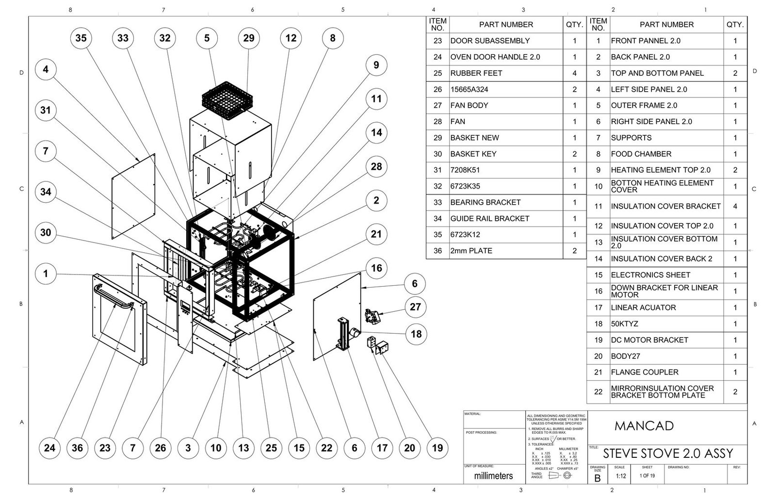
Countertop convection oven sheet metal assembly drawing with fabricated panels and internal components
Engineering evidence from the existing project portfolio
Overview

SolidWorks sheet metal design for brackets, chassis, guards, panels, cabinets and complete fabricated assemblies. Parts are developed with realistic material thickness, bend radius, K-factor or bend allowance, relief geometry, hems, hardware and weld or fastening access.

Assemblies are reviewed for tolerance accumulation, tool clearance, installation order and practical fabrication. Manufacturing support can include native sheet metal CAD, flat patterns, fabrication-ready DXF files, folded STEP models, production drawings, bend notes, cut lists and BOMs.

Supplier feedback from laser cutters, press-brake operators, welders and powder coat vendors can be incorporated through controlled revisions before the drawing package is released.

Deliverables
  • Native sheet metal parts
  • Folded assembly models
  • Flat patterns
  • Fabrication DXF files
  • Bend notes and allowances
  • Cut lists and BOM
  • Production drawings
  • Supplier revisions

Typical Applications

  • Chassis and cabinets
  • Machine guards
  • Equipment panels
  • Fabricated product assemblies

Software Used

  • SolidWorks Sheet Metal
  • AutoCAD
  • eDrawings

Manufacturing Outputs

  • Flat-pattern DXF
  • Folded STEP models
  • PDF fabrication drawings
  • BOM and cut lists
Revision Process

Material thickness, bend radius, hardware, weld access and assembly sequence are reviewed before release. Fabricator feedback is incorporated into the native sheet metal model before updated flats and drawings are issued.

Countertop convection oven assembly drawing with sheet metal components
Related Project

Countertop Convection Oven

A fabrication-led appliance assembly combining formed panels, internal brackets, hardware access and manufacturing documentation.

View Portfolio
Ready to discuss your project?

Start with the engineering problem and the files already available.

Injection Molding Design Services

  • Wall thickness and draft
  • Ribs, bosses and snap fits
  • Parting and tooling direction
  • Warpage and undercut review
  • Supplier-ready CAD
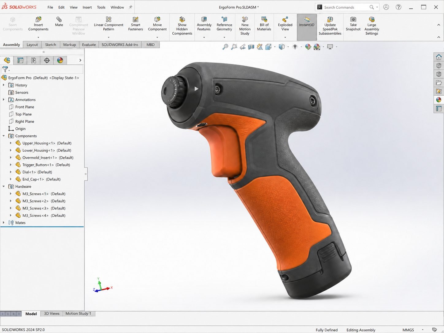
Ergonomic handheld power tool housing with molded shell, internal packaging and assembly features
Engineering evidence from the existing project portfolio
Overview

Injection molding design for plastic housings, covers, clips, consumer products and functional components. Injection molded parts are developed around consistent wall thickness, draft angles, ribs, bosses, snap fits, shutoffs, parting direction, likely gate and ejector constraints, fastening and assembly access.

The review also considers sinks, warpage risk, undercuts, tooling direction and how cosmetic or sealing surfaces affect mold decisions. Existing CAD can be corrected after mold-maker feedback, or molding constraints can be built into the concept from the start.

Deliverables may include revised parametric CAD, STEP files, section views, critical dimensions and documented questions for the supplier before tooling release.

Deliverables
  • Draft and wall review
  • Ribs and boss design
  • Snap-fit development
  • Parting direction review
  • Undercut assessment
  • Tooling feedback resolution
  • Supplier-ready CAD
  • Controlled revisions

Typical Applications

  • Consumer housings
  • Handheld products
  • Medical enclosures
  • Functional plastic components

Software Used

  • SolidWorks
  • Fusion 360
  • SolidWorks evaluation tools

Manufacturing Outputs

  • Native parametric CAD
  • Mold-ready STEP files
  • Critical section views
  • Supplier review package
Revision Process

Mold-maker comments are checked against functional, cosmetic and sealing requirements. Approved changes are applied to the parametric model, reviewed in section and released as a controlled supplier package.

Ergonomic handheld power tool housing and internal component packaging
Related Project

Handheld Power Tool Housing

An ergonomic enclosure developed around internal components, grip geometry, wall thickness, fastening and practical molded-part separation.

View Portfolio
Ready to discuss your project?

Start with the engineering problem and the files already available.

Manufacturing Drawings and GD&T Services

  • Production drawings
  • GD&T services
  • Tolerance analysis
  • BOMs and revision data
  • Inspection-ready files
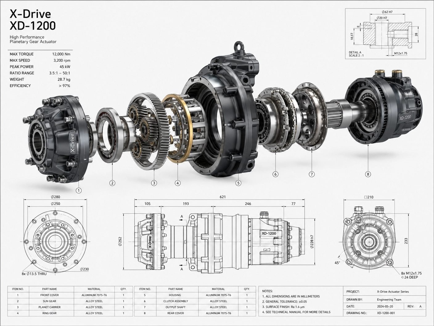
Planetary gear actuator exploded assembly and GD&T manufacturing drawing
Engineering evidence from the existing project portfolio
Overview

Manufacturing drawings for CNC machined, injection molded and sheet metal parts, plus assembly drawings for production and inspection. Engineering drawings define design intent with appropriate views, datums, dimensions, fits, tolerances, GD&T, materials, finishes, process notes, BOMs and revision information.

Critical features are selected from function and assembly requirements instead of dimensioning every visible edge or accepting default CAD tolerances. GD&T services and tolerance analysis help suppliers understand what must be controlled, what can vary and how parts will be verified.

The resulting PDF, DWG, DXF and native drawing packages support quotation, first-article review, inspection and a dependable manufacturing handoff.

Deliverables
  • Part manufacturing drawings
  • Assembly drawings
  • GD&T callouts
  • Datum strategy
  • Fits and tolerances
  • BOM and balloons
  • Material and finish notes
  • Revision control

Typical Applications

  • CNC machined parts
  • Mechanical assemblies
  • Sheet metal fabrication
  • Supplier inspection packages

Software Used

  • SolidWorks Drawings
  • AutoCAD
  • eDrawings

Manufacturing Outputs

  • SLDDRW source files
  • PDF drawing packages
  • DWG and DXF files
  • Released BOM and revision record
Revision Process

Drawing changes remain linked to the approved model. Dimensions, datums, notes and revision tables are reviewed together so suppliers receive one coherent definition of the released part or assembly.

Planetary gear actuator exploded assembly and geometric dimensioning drawing
Related Project

Planetary Gear Actuator

A precision assembly documented with exploded views, item identification, manufacturing dimensions and GD&T controls.

View Portfolio
Ready to discuss your project?

Start with the engineering problem and the files already available.

Finite Element Analysis Services

  • Structural and thermal FEA
  • Loads and constraints
  • Mesh quality review
  • Stress and temperature results
  • Design validation
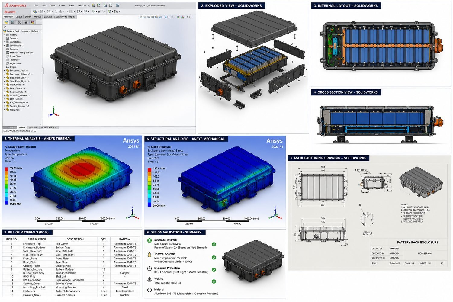
EV battery pack enclosure with structural and thermal finite element analysis contour plots
Engineering evidence from the existing project portfolio
Overview

Structural and thermal finite element analysis for brackets, enclosures, actuators, frames and load-bearing mechanical assemblies. FEA begins with the engineering question: expected loads, constraints, contacts, materials, operating conditions and the failure mode that matters.

Geometry is simplified deliberately, mesh quality and sensitivity are reviewed, and results are interpreted against stress, displacement, temperature or factor-of-safety requirements. Assumptions and limitations are documented so a contour plot is not mistaken for design proof.

Analysis findings feed back into CAD changes, design validation, prototype testing and review decisions before expensive tooling, CNC machining or fabrication is authorized.

Deliverables
  • Structural FEA
  • Thermal analysis
  • Load-case definition
  • Boundary-condition review
  • Mesh convergence check
  • Stress and displacement results
  • Design recommendations
  • Technical report

Typical Applications

  • Load-bearing components
  • Equipment structures
  • Thermal enclosures
  • Design validation before tooling

Software Used

  • SolidWorks Simulation
  • ANSYS Mechanical
  • ANSYS Thermal

Manufacturing Outputs

  • Contour plots
  • Result tables
  • PDF engineering report
  • Revised validation CAD
Revision Process

Loads, restraints, contacts, materials and acceptance criteria are agreed before solving. Results are translated into specific design changes, then the revised model is checked against the same documented validation basis.

Aluminum EV battery pack enclosure with structural and thermal analysis
Related Project

EV Battery Pack Enclosure

A machined aluminum enclosure assessed for thermal performance, structural safety and production documentation before release.

View Portfolio
Ready to discuss your project?

Start with the engineering problem and the files already available.

Common engineering workflows

Combine services around the decision the product needs next.

Each service has a focused scope for search and procurement clarity, but real product development usually combines several disciplines. The engagement can begin with one urgent deliverable, then expand only when the next engineering decision requires it. Requirements, assumptions, design reviews, supplier responses and approved revisions remain connected so manufacturing teams receive a coherent handoff rather than disconnected CAD files.

Concept to prototype

Product design, CAD modeling and prototype development.

Resolve the product architecture and prepare editable CAD for a focused first build.

Useful when a new product needs its mechanical architecture resolved before a first build. The workflow combines product design engineering, parametric CAD, internal packaging, mechanical assembly logic and early DFM review. Prototype files are prepared for the selected rapid prototyping or machining process, then fit, function and assembly findings are captured in a design review. The output is an editable model and a clear revision path, not a one-off prototype file that must be rebuilt before production.

Design validation

FEA, tolerance review and controlled engineering revisions.

Create evidence for critical design decisions before committing to tooling or production.

Useful when a team needs evidence before committing to tooling or production. The scope can combine finite element analysis, tolerance analysis, interface checks, material review and physical prototype findings. Loads, boundary conditions, acceptance criteria and uncertain inputs are documented before simulation begins. Results are translated into specific CAD changes, then checked through a repeatable review and revision process. The manufacturing outcome is a better-supported design decision and a clear record of what was validated, what changed and what still requires physical testing.

Not sure where to start

Send the engineering problem and receive a practical first step.

A short brief, reference image, drawing or existing CAD file is enough to begin.

  • NDA Available
  • Manufacturing Ready Files
  • Worldwide Support
  • 24 Hour Response

A short brief, reference image, drawing or existing CAD file is enough to begin. Talha will identify the missing inputs, immediate technical risk and most useful first deliverable, whether that is a CAD model, DFM review, production drawing, tolerance check or FEA study. Confidential concepts, product files and supplier information can be reviewed under an NDA when required. Share the project requirements for a focused scope, deliverables and review plan.