Freelance Mechanical Design Engineer

Mechanical Design Engineer for Production Ready Products.

Product development, SolidWorks CAD, DFA/DFM and manufacturing support from prototype to production for startups, product teams and manufacturers worldwide.

Share your requirements and receive a clear engineering scope, deliverables and next step.
Talha Javed Malik, registered mechanical design engineer and SolidWorks consultant
Talha Javed Malik Islamabad, supporting clients worldwide
Core platform SolidWorks CAD
Manufacturing DFM and GD&T
Validation Structural and thermal FEA
Delivery model Worldwide remote collaboration
Mechanical design services

Focused engineering support for each stage of development.

Choose focused CAD design services or combine several engineering design services into one product development scope. Every service page explains the problem, deliverables, workflow and relevant project evidence.

01

SolidWorks Design Services

Parametric SolidWorks modeling, assemblies and drawing packages for product teams who need CAD that a supplier can actually quote and build from, not just a file that opens cleanly on screen.

View service
02

Mechanical CAD Services

Complete mechanical CAD, from a rough concept or sketch through detailed assemblies, mechanism design and the documentation a manufacturer needs to quote and build.

View service
03

Product Design Engineering

Complete product design engineering, from a rough concept, reference image or early prototype through resolved industrial design, mechanical CAD, DFM and a documentation package ready for manufacturers.

View service
04

Design for Manufacturing Services

Design for Manufacturing review for injection molded plastics, CNC machined parts and sheet metal assemblies, built into the CAD process from the first model instead of added as an afterthought.

View service
05

Sheet Metal Design Services

Sheet metal parts and assemblies modeled in SolidWorks with real bend allowances, correctly developed flat patterns, and DXF files ready for fabrication, not just a folded solid that looks right on screen.

View service
06

Injection Molding Design Services

Injection molded plastic part design for consumer products and hardware, with wall thickness, draft angles, snap fit geometry and rib structure resolved from the concept stage instead of discovered by a mold maker.

View service
07

Manufacturing Drawing Services and GD&T

Dimensioned manufacturing drawings and GD&T for machined, molded and sheet metal parts, prepared for real quoting and inspection, not automatically generated views with default tolerances left in place.

View service
08

Finite Element Analysis Services

Structural and thermal finite element analysis for enclosures, brackets, actuators and load bearing assemblies, used to validate a design decision before it is committed to tooling or machining.

View service
Who the work supports

Engineering capacity that fits the stage of the product.

Projects are structured for teams that need practical mechanical design support without adding unnecessary process or permanent overhead.

Startups and founders

Turn an early idea into reviewable CAD.

Translate sketches, requirements and reference products into a clear concept, assembly structure and prototype ready design.

Product teams

Add focused CAD and DFM capacity.

Support an existing team with detailed modeling, engineering review, simulation and documentation during busy development stages.

Manufacturers and fabricators

Prepare files that are easier to quote and build.

Resolve dimensions, tolerances, flat patterns, bill of materials and supplier feedback before production release.

Engineering design consultancy

Mechanical design decisions backed by manufacturing context.

Focused support connects the product requirement to the CAD model, the manufacturing process and the final inspection document, reducing ambiguity before prototyping or production.

01

Why Work With Me

You work directly with the engineer developing the model. Requirements, tradeoffs, revisions and supplier feedback stay in one traceable conversation, with scope and deliverables agreed before detailed work begins.

About the engineer
02

Engineering Expertise

Product development services cover mechanisms, enclosures, assemblies, interfaces sensitive to tolerance, material selection, structural or thermal FEA and CAD models ready for production from concept through release.

Explore product design engineering
03

Software Expertise

SolidWorks is the primary tool for parametric parts, configurations, assemblies, sheet metal, drawings and simulation. AutoCAD supports practical DWG and DXF work; Fusion 360 is available when its workflow better fits the project.

Review SolidWorks design services
04

Deliverables

Handoffs can include SLDPRT, SLDASM, STEP, STL, DWG, DXF and PDF files, plus a BOM, manufacturing drawings, assembly drawings, exploded views and controlled engineering documentation.

See drawing and GD&T deliverables
05

Engineering Standards

Drawings use relevant ASME Y14 conventions for dimensioning and GD&T where required. Datums, fits, tolerances, materials, finishes and revision status are applied to suit function and manufacturing, not as decorative notes.

Explore DFM services
06

Quality Assurance

Release checks review model integrity, interfaces, clearances, fasteners, assembly access, drawing to model consistency and file completeness. Critical assumptions and open supplier questions are documented before handoff.

Review engineering case studies
Where the experience applies

Industries served and manufacturing knowledge.

Relevant experience spans mechanical design projects for varied products and processes. Practical engineering notes and future technical articles will be available in the engineering resources and blog.

Application experience

Industries Served

Consumer products, industrial equipment, automation, medical devices, furniture, electronics, manufacturing, renewable energy, packaging and industrial machinery.

Process awareness

Manufacturing Knowledge

Injection molding, CNC machining, sheet metal fabrication, additive prototypes and mixed material assemblies each require different rules for access, tolerances, draft, bends, fastening and inspection.

Production readiness

Prototype learning carried into release.

Prototype findings, DFA/DFM feedback and supplier constraints are converted into controlled model and drawing revisions so the production package reflects what was actually learned.

Selected work

Explore projects visually.

Preview the work from the project dock, then open a case study for the engineering brief, specifications and original presentation.

14 / 14 Bench Grinder Assembly for AI Training Dataset
Bench grinder assembly portfolio board
Prototype to production engineering

Design Process: a practical five-step workflow.

Every stage produces a clear decision, review point or manufacturing deliverable.

01
Requirements

Define the product

Fit, function, references, materials and target dimensions are agreed before geometry begins.

02
CAD development

Build the CAD system

Parametric parts, multi-part assemblies, mechanisms, interfaces and fasteners are developed in SolidWorks or Fusion 360.

03
DFM review

Review manufacturing risk

Moldability, machining access, sheet metal bends, fit relationships and assembly sequence are reviewed before release.

04
Simulation and checks

Validate performance

Structural, thermal and tolerance checks are completed where the product needs evidence rather than assumption.

05
Production documentation

Document the handoff

Drawings, GD&T, bills of materials, exploded views and exchange files are packaged for suppliers and production.

01

Product and Consumer Design

Consumer products, wearable electronics and electromechanical systems designed around real use, assembly and production.

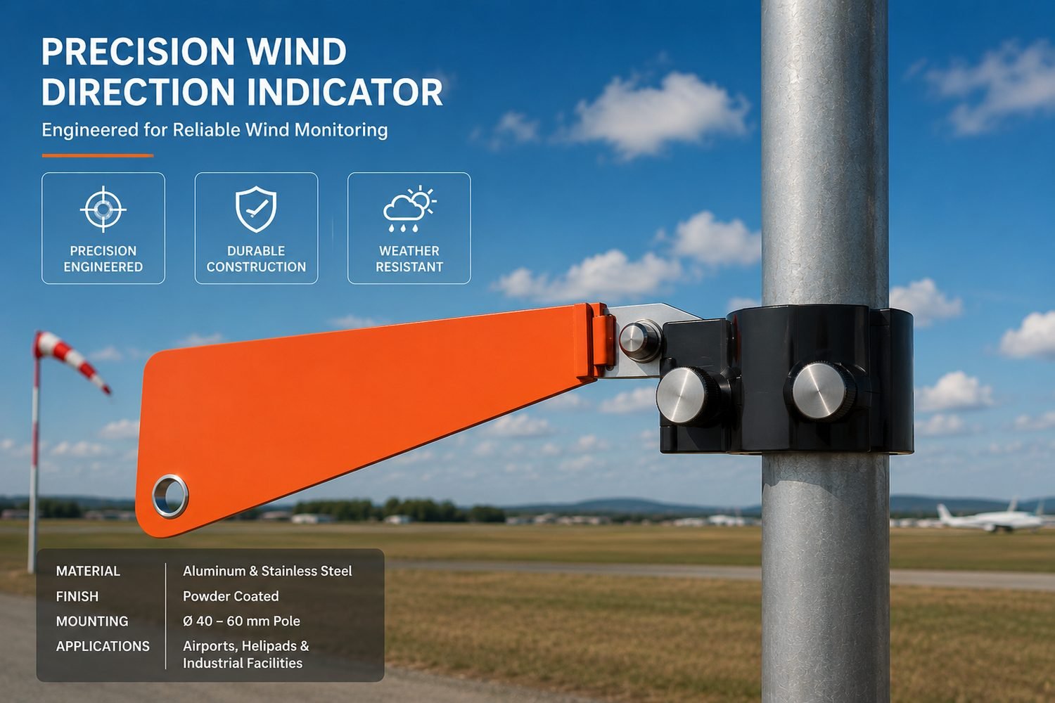
Precision wind direction indicator mounted on pole
Project 02: Product Design

Precision Wind Direction Indicator

Challenge: expose direction clearly outdoors. Solution: weatherproof housing and low friction vane assembly. Outcome: a reviewable instrument design for airports, helipads and industrial rooftops.

View case study
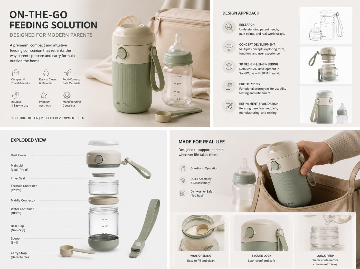
On the go baby formula feeding container exploded view
Project 03: Consumer Product

On the Go Baby Formula Feeding Container

Challenge: separate formula and water during travel. Solution: a sealed modular container with controlled interfaces. Outcome: a compact assembly designed for filling, cleaning and transport.

View case study
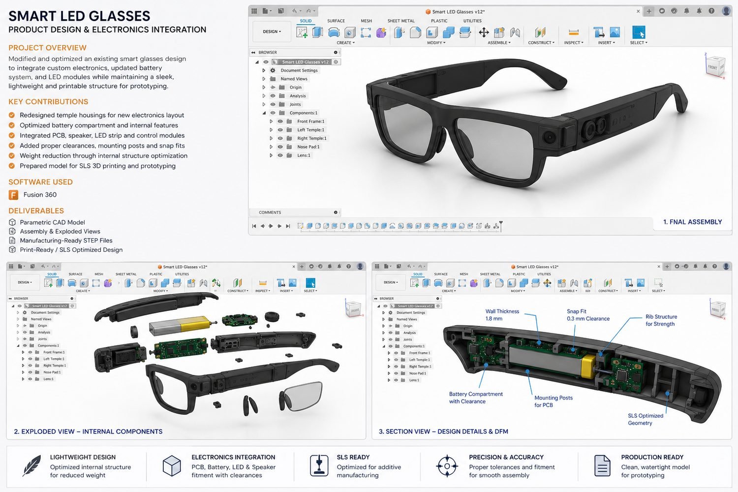
Smart LED glasses product design with electronics integration exploded and section views
Project 05: Electronics Integration

Smart LED Glasses

Challenge: package electronics within wearable geometry. Solution: coordinated PCB, battery, LED and speaker housings. Outcome: an integrated assembly prepared for SLS production.

View case study
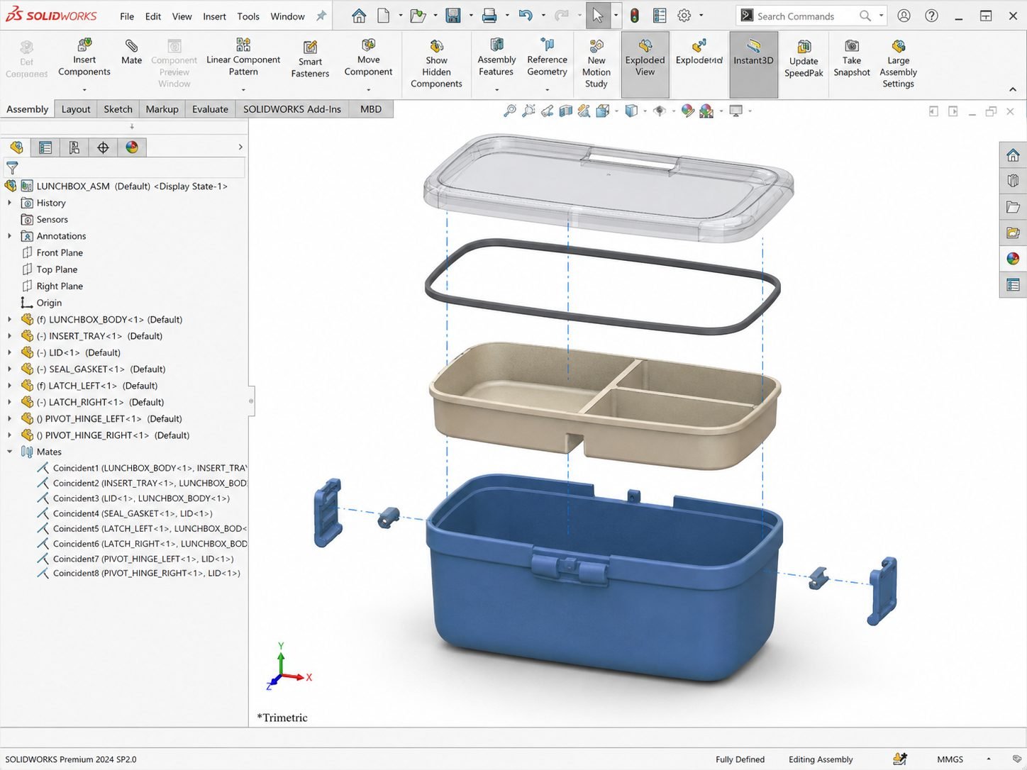
Modular lunchbox system exploded SolidWorks assembly
Project 06: Assembly Design

Modular Lunchbox System

Challenge: create modular storage with dependable closure. Solution: four gasketed compartments and dual latches. Outcome: a resolved assembly with supplier ready exploded documentation.

View case study
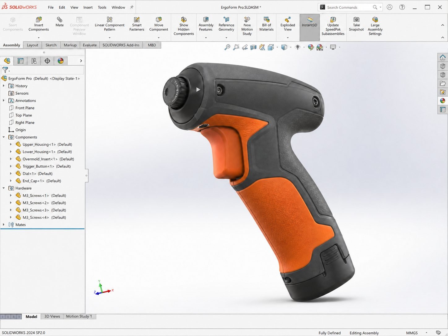
Ergonomic handheld power tool housing final assembly render
Project 07: Ergonomic Design

Ergonomic Handheld Power Tool Housing

Challenge: balance grip comfort with internal packaging. Solution: a TPE overmold housing around electronics and heat set inserts. Outcome: an ergonomic power tool enclosure ready for assembly.

View case study
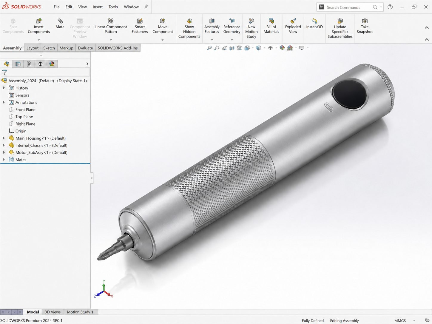
Precision cordless screwdriver final assembly
Project 08: Mechanism Design

Precision Cordless Screwdriver

Challenge: package a compact configurable drivetrain. Solution: coordinated planetary gearing, battery management and control electronics. Outcome: one controlled assembly supporting multiple product configurations.

View case study
02

Industrial and Mechanical Systems

Mechanical assemblies, structural products and power transmission systems developed with realistic interfaces and validation.
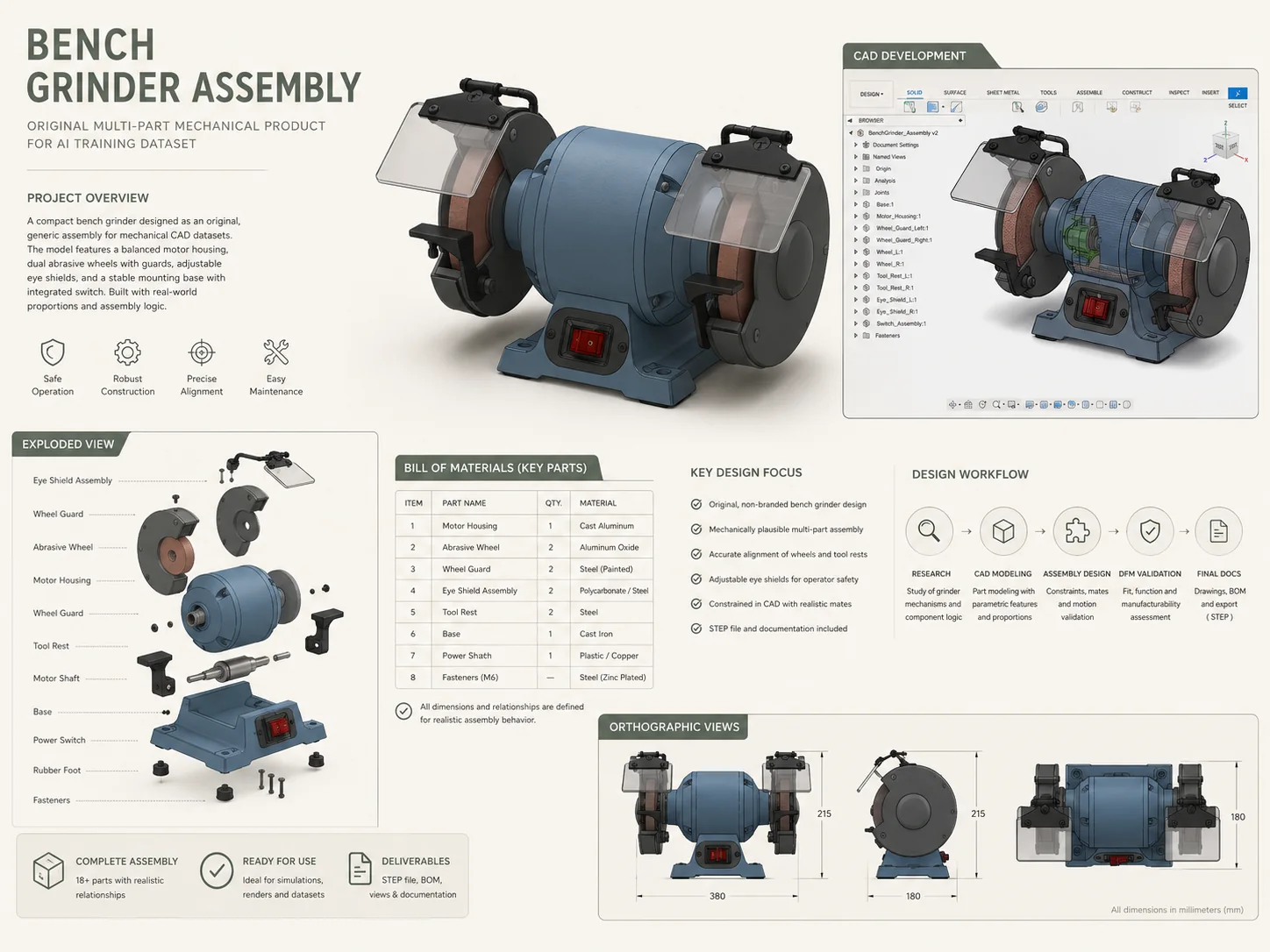
Bench grinder assembly portfolio board
Project 14: Multi Part Assembly

Bench Grinder Assembly for AI Training Dataset

Challenge: create believable original mechanical training data. Solution: a bench grinder with more than 18 realistic parts. Outcome: documented assembly logic, BOM and STEP export.

View case study

Gothic tower clock face photorealistic render with ornate gold and black dial detailing
Project 01: Real Time Software

Gothic Tower Clock Display System

Challenge: preserve ornate clock detail on a large outdoor display. Solution: custom real time graphics mapped to 2048 × 2048 pixels. Outcome: legible day and night rendering.

View case study
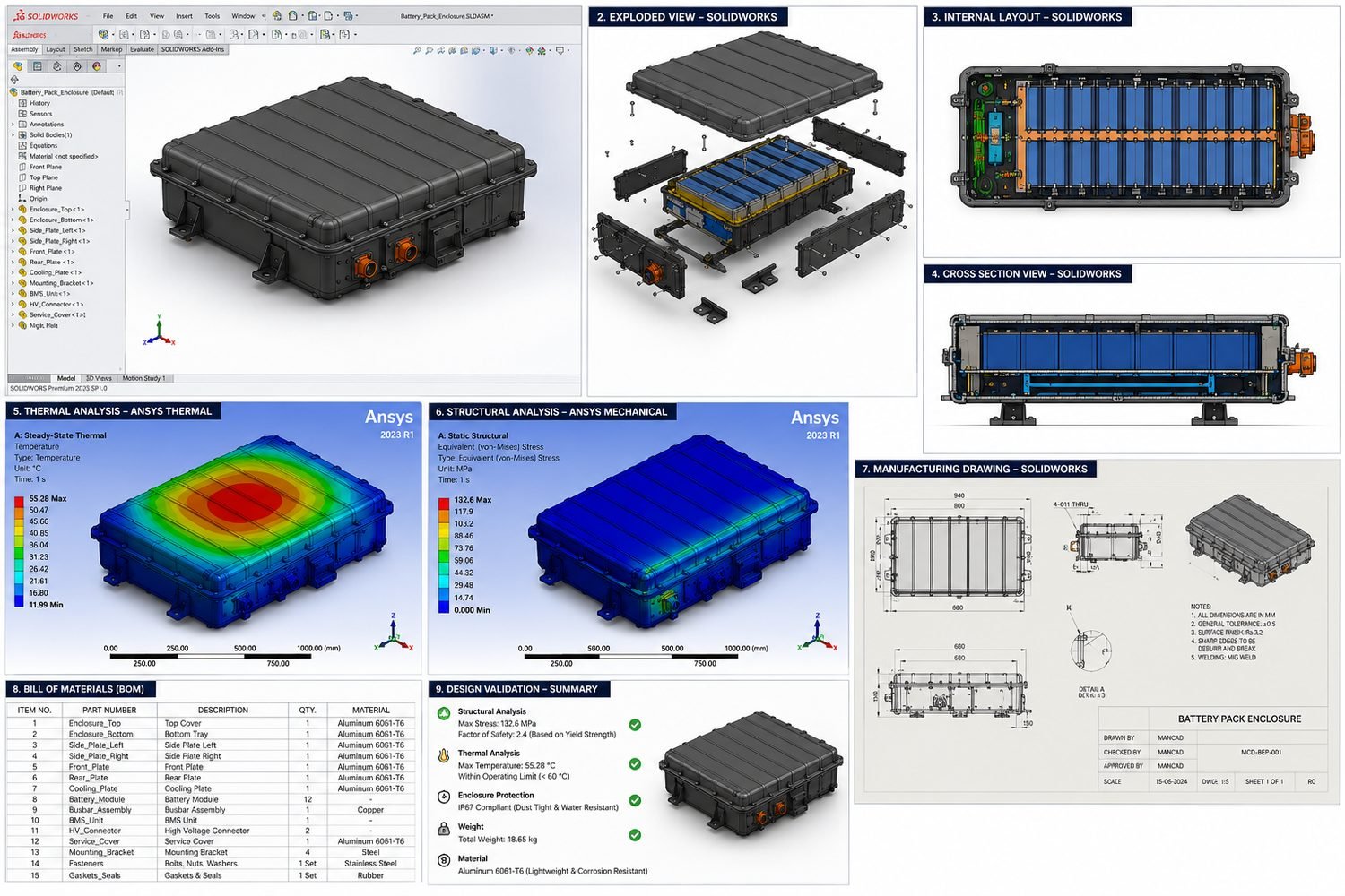
EV battery pack enclosure SolidWorks assembly with thermal and structural FEA
Project 04: FEA, Thermal and Structural

EV Battery Pack Enclosure

Challenge: package and protect twelve battery modules. Solution: an aluminum enclosure evaluated structurally and thermally. Outcome: validated CAD supported by a complete manufacturing drawing package.

View case study
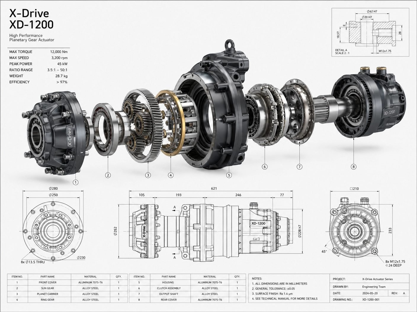
Planetary gear actuator manufacturing drawing exploded view
Project 09: Power Transmission

Planetary Gear Actuator

Challenge: transmit up to 12,000 Nm through precision components. Solution: a toleranced planetary driveline with defined interfaces. Outcome: GD&T and production drawings for machining review.

View case study
03

Precision and Manufacturing Documentation

Machined enclosures, sheet metal assemblies, GD&T and supplier ready manufacturing drawing packages.
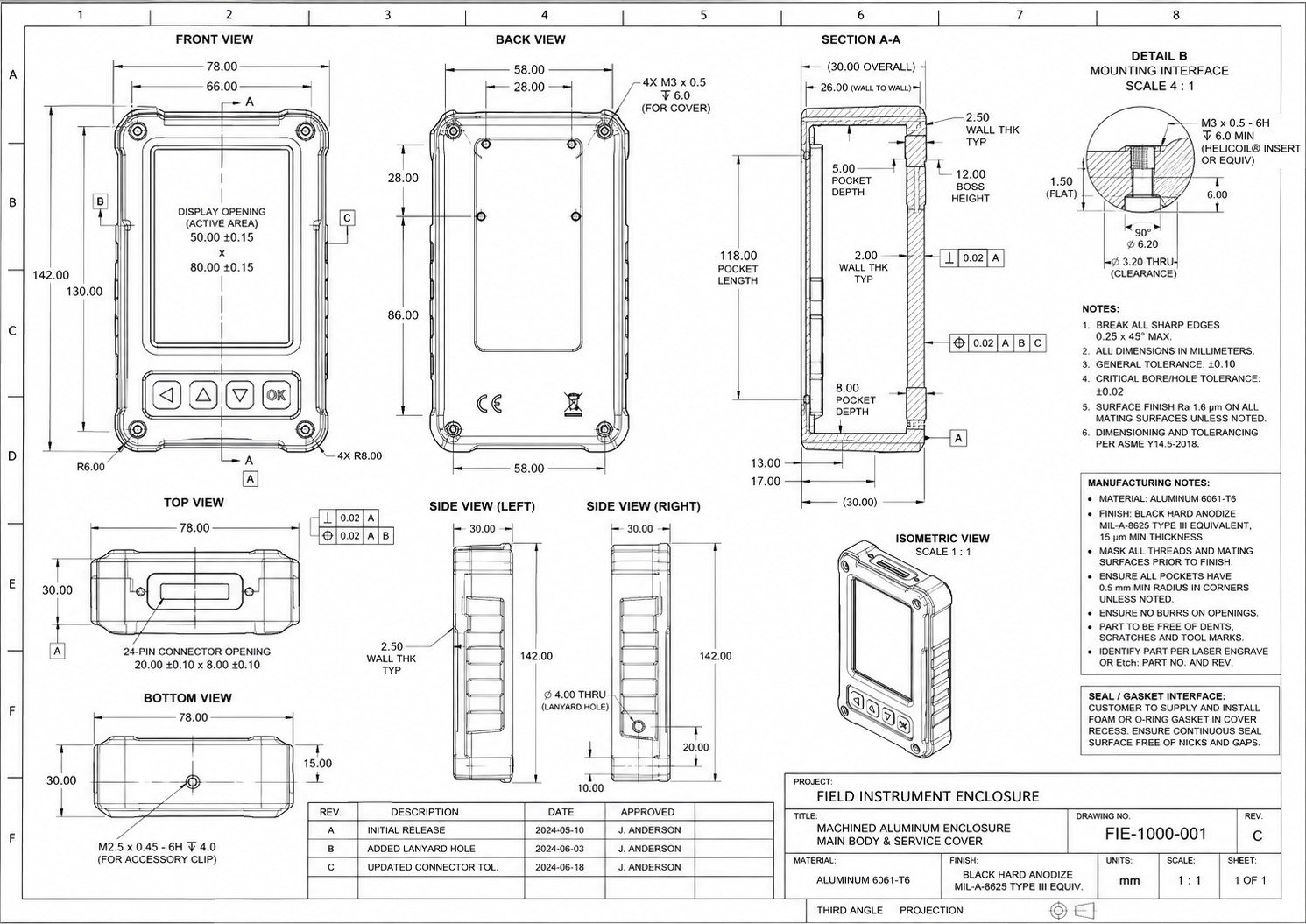
Field instrument enclosure machined aluminum drawing with front back and section views
Project 10: Precision Machining

Rugged Handheld Instrument Enclosure

Challenge: protect a field display while controlling critical interfaces. Solution: a hard anodized machined enclosure with reinforced mounting points. Outcome: drawings ready for inspection of tightly toleranced features.

View case study
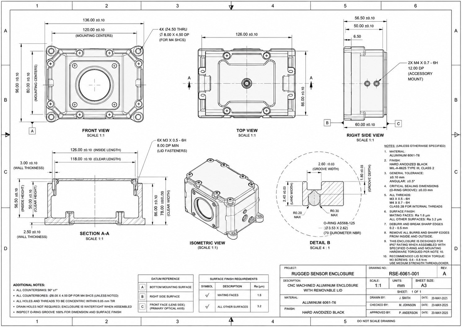
Rugged sensor enclosure CNC machined aluminum drawing with O ring groove detail
Project 11: IP67 Sealing

Rugged Sensor Enclosure

Challenge: seal sensitive optical hardware. Solution: a machined enclosure with an AS568 O ring groove and controlled mating surfaces. Outcome: a package intended for IP67 supplier review.

View case study
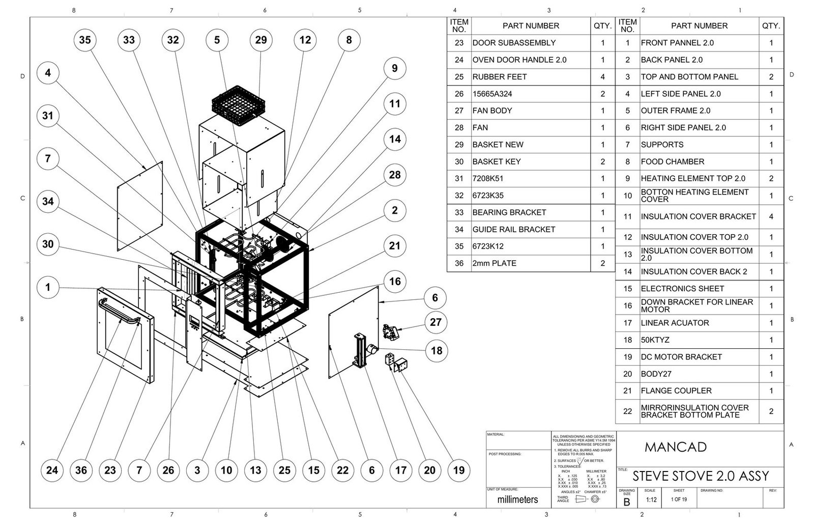
Countertop convection oven full assembly manufacturing drawing
Project 12: Sheet Metal Design

Countertop Convection Oven Assembly

Challenge: coordinate a complex appliance with mixed parts. Solution: resolved sheet metal, insulation, frame, door and actuator interfaces. Outcome: a 19 sheet package with a 36 item BOM.

View case study
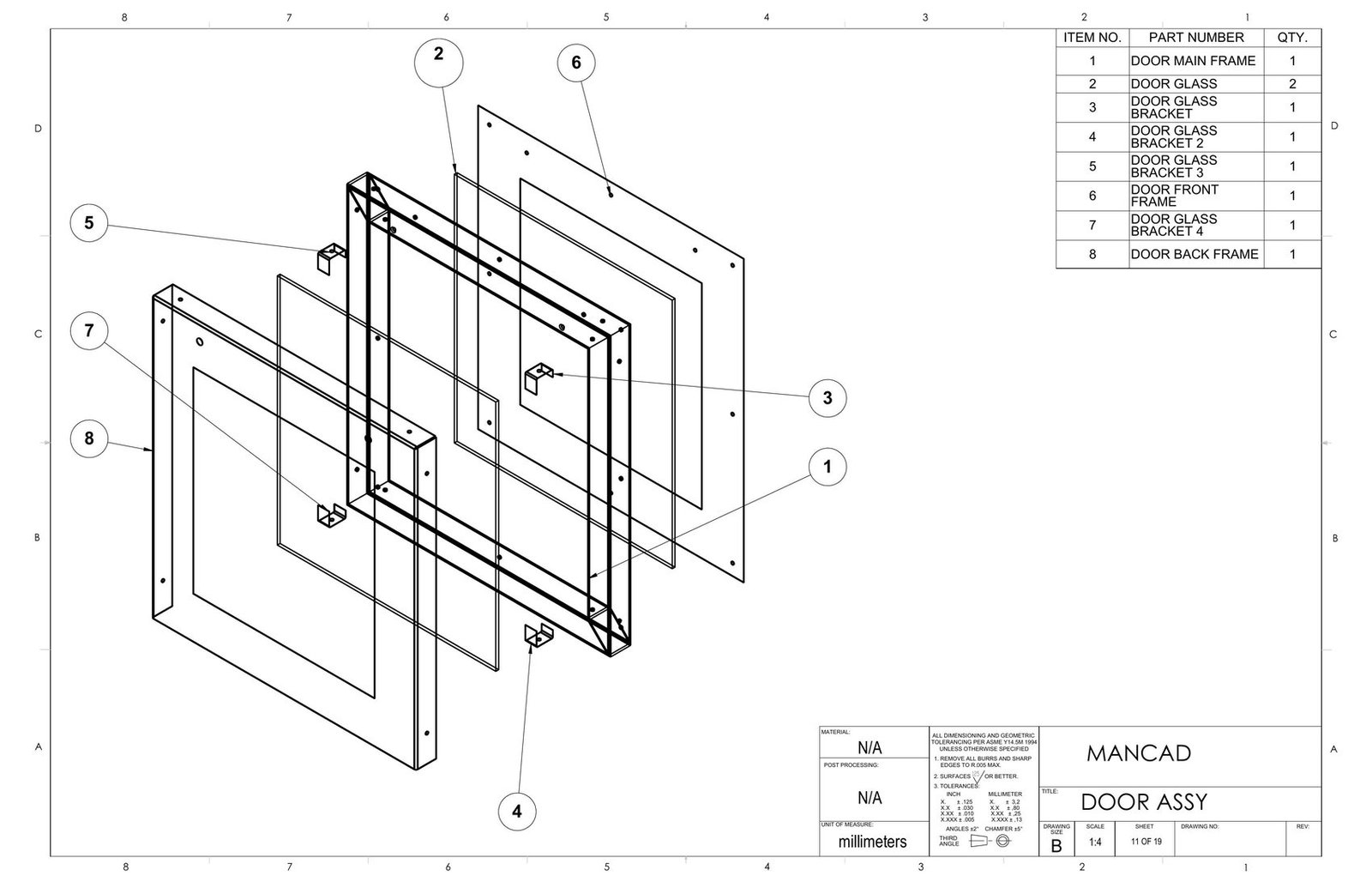
Oven door subassembly and food chamber drawing
Project 13: Sheet Metal

Oven Door and Food Chamber Subassembly

Challenge: coordinate glass, steel, insulation and motion. Solution: an eight part door and dimensioned AISI 316 chamber. Outcome: defined fabrication geometry and actuator interfaces.

View case study
Mechanical design consultant Talha Javed Malik reviewing product engineering work
About Talha

Factory floor thinking from the first sketch.

Talha Javed Malik is a registered mechanical engineer, product development engineer and mechanical design consultant based in Islamabad, working remotely across product design, SolidWorks CAD, DFM, FEA and production documentation.

Projects range from consumer products and wearable electronics to EV hardware, mechanisms, precision enclosures and complete sheet metal manufacturing packages.

14 Selected projects
FEA Structural and thermal
DFM Manufacturing review
GD&T Production drawings
Worldwide engineering support

Global Collaboration and the Benefits of Working Remotely.

A remote mechanical design engineer gives startups and manufacturers flexible access to specialist CAD, DFM, FEA and documentation capacity without adding permanent overhead. Written review points, shared files and time zone handoffs create a clear record of decisions for teams in the USA, Australia and worldwide.

Before we begin

Common project questions, answered clearly.

Quick answers about scope, deliverables, collaboration and manufacturing support.

What does a Mechanical Design Engineer do?

A mechanical design engineer converts product requirements into functional, manufacturable parts and assemblies. The work can include concept development, 3D CAD, mechanism design, material and process decisions, tolerance definition, DFM, validation and production drawings.

What files will I receive?

The agreed handoff can include native SLDPRT, SLDASM and SLDDRW files, STEP, STL, DWG, DXF and PDF files, plus bills of materials, manufacturing drawings, assembly drawings, exploded views and engineering documentation.

Can you redesign existing products?

Yes. Existing CAD, prototypes, scans, photographs or drawings can be reviewed to correct failures, simplify assembly, reduce manufacturing cost or adapt the design to a new process or requirement.

Can you sign an NDA?

Yes. An NDA can be signed before confidential concepts, product files or supplier information are shared. The project can then continue through secure, agreed file sharing and communication channels.

Which CAD software do you use?

SolidWorks is the primary platform for parametric parts, assemblies, sheet metal, drawings and simulation. AutoCAD supports compatible 2D DWG and DXF work, while Fusion 360 is available when it is a better fit for the project.

Do you support startups?

Yes. Mechanical design engineering for startups can begin with sketches and requirements, then progress through concept CAD, prototype files, design reviews, DFM and a controlled production handoff.

Can you prepare manufacturing drawings?

Yes. Manufacturing and assembly drawings can include dimensions, datums, fits, tolerances, GD&T, materials, finishes, weld or bend notes, bills of materials and revision information appropriate to the process.

Do you optimize products for injection molding?

Yes. Injection molding design reviews address draft, wall thickness, ribs, bosses, snap fits, parting direction, undercuts, fastening and assembly so tooling risks are found before mold release.

Can you collaborate with manufacturers?

Yes. Supplier questions, DFM feedback, quotation clarifications, prototype findings and drawing revisions can be managed directly so design intent stays clear through production preparation.

How does the engineering process work?

The process follows five controlled stages: define requirements, build the CAD system, review manufacturing risk, validate critical performance and release an agreed production documentation package.

Start a conversation

Choose a direct way to start the conversation.

WhatsApp, Upwork and email are available for project enquiries worldwide.

Useful project brief

A clear first message saves review time.

  • Product objective and main function
  • Sketches, images, scans or existing CAD
  • Known dimensions, materials and manufacturing method
  • Required outputs such as STEP, drawings, BOM or FEA
  • Target dates and supplier constraints
Ready to move forward

Let's make the next engineering decision clear.

Share the product stage, current files and the result you need.

Project 01

Gothic Tower Clock Display System

A custom engineering and real time display build for architectural signage: a bespoke real time software and display engineering build for a large scale Gothic style tower clock, developed to run natively on a NovaStar TB60 controller driving a 2048×2048 pixel P3.91 outdoor LED wall. The clock face was modeled and textured with full Gothic ironwork detailing, including a rose window center, gold filigree numerals and ornate hands, then rigged to a custom real time engine with an automatic day and night rendering mode: crisp, high contrast matte faces for daylight legibility, and a softer backlit glow after dark to avoid glare for nearby drivers and pedestrians. Every asset was mathematically mapped to the exact LED pixel grid for edge to edge sharpness with minimal scaling distortion, and the software was built to hold up to continuous 24/7 outdoor runtime.

Gothic tower clock face photorealistic render with ornate gold and black dial detailing
Photorealistic render of the gothic tower clock face, mathematically mapped to a 2048×2048 px P3.91 outdoor LED wall.
Real Time Software LED Display Engineering Day and Night Rendering
Display 2048×2048 px, P3.91 LED
Controller NovaStar TB60
Project 02

Precision Wind Direction Indicator

Outdoor product design engineering for precision instrumentation: a weatherproof wind vane instrument engineered for airports, helipads and industrial rooftops. Aluminum and stainless construction with a powder coated finish and a two knob pole clamp sized for 40 to 60 mm masts, built for precision reading and low maintenance outdoor service.

Precision wind direction indicator mounted on pole
Assembly render showing a powder coated aluminum vane on a two knob pole clamp for outdoor deployment.
Product Design Outdoor Hardware Aluminum + Stainless
Mount Ø40 to 60mm pole
Finish Powder coated
Project 03

On the Go Baby Formula Feeding Container

Consumer product design and DFM for injection molding: a compact, travel ready feeding container built around a 120 ml formula chamber and 180 ml water reservoir, with a leak resistant lid and a one hand secure lock. Taken through research, concept exploration and SolidWorks development with DFM in mind, finished with a detachable strap for diaper bag carry.

On the go baby formula feeding container exploded view
Design approach, exploded BOM and real life carry context for the feeding container.
Consumer Product Industrial Design DFM
Capacity 120ml + 180ml
Care Dishwasher safe
Project 04

EV Battery Pack Enclosure

EV battery enclosure design with FEA thermal and structural validation: a 12 module lithium battery enclosure machined from 6061 T6 aluminum, designed toward an IP67 rating with a structural Factor of Safety of 2.4. Ansys Thermal and Ansys Mechanical studies indicated a 55.3 °C peak temperature and 132.6 MPa peak stress, both inside spec, before the 15 item BOM and manufacturing drawing were prepared.

EV battery pack enclosure SolidWorks assembly with thermal and structural FEA
Assembly, exploded view, thermal & structural FEA, manufacturing drawing and validation summary.
FEA, Thermal and Structural EV Hardware Manufacturing Drawing
Max stress 132.6 MPa (FoS 2.4)
Max temp 55.28 °C
Project 05

Smart LED Glasses

Wearable electronics product design for SLS 3D printing: reengineered the temple housings of an existing smart glasses platform to fit a custom PCB, battery, LED strip and speaker. Wall thickness, snap fit clearance and rib structure were tuned specifically for SLS 3D printing, keeping the frame light and comfortable enough for all day wear.

Smart LED glasses product design with electronics integration exploded and section views
Final assembly, internal exploded components, and section view showing wall thickness and snap fit detail.
Electronics Integration Wearable Tech SLS Printing
Wall thickness 1.8mm
Software Fusion 360
Project 06

Modular Lunchbox System

Consumer product assembly design with sealing and latch mechanisms: a four compartment lunchbox assembly with a gasketed, leak resistant lid, dual pivot latches and a removable insert tray, fully defined in SolidWorks with mate driven exploded documentation ready for supplier handoff.

Modular lunchbox system exploded SolidWorks assembly
Exploded assembly: lid, seal gasket, insert tray, dual latches and pivot hinges.
Assembly Design Sealing Systems Consumer Product
Compartments 4
Software SolidWorks 2024
Project 07

Ergonomic Handheld Power Tool Housing

Ergonomic electromechanical product design for injection molding: a pistol grip housing for a handheld power tool, built around an overmolded soft touch grip, a rotary dial, trigger button and PCB mount plate. Every subassembly, including the upper and lower housing, battery pack, switch assembly and LED light pipe, is captured in the exploded release drawing for a clean supplier handoff.

Ergonomic handheld power tool housing final assembly render
Handheld power tool housing exploded view with PCB battery and switch assembly
Final housing assembly (left) and full exploded release showing PCB, battery pack and switch assembly (right).
Ergonomic Design Overmold Electromechanical
Grip TPE overmold insert
Assembly M3 heat set inserts
Project 08

Precision Cordless Screwdriver

Mechanism design engineering for configurable electromechanical products: a configurable cordless driver built around a 7.2 to 1 planetary gearbox and a coreless 12V, 16,000 RPM DC motor, powered by an integrated BMS lithium cell. A custom 32 bit control PCB drives an LED ring indicator and haptic feedback, with Precision, High Torque and Service configurations managed from one master model.

Precision cordless screwdriver final assembly
Cordless screwdriver exploded view showing planetary gearbox, DC motor and lithium battery
Final housing (left) and driveline exploded view: planetary gearbox, DC motor, battery and control PCB (right).
Mechanism Design Electromechanical Configuration Mgmt.
Motor 12V, 16,000 RPM coreless
Battery 12V 800mAh / 9.6Wh
Project 09

Planetary Gear Actuator

Precision machining and GD&T drawing package for power transmission hardware: a high performance planetary actuator designed for a target torque of 12,000 Nm at up to 3,200 rpm and 45 kW peak power, with an eight part driveline including the sun gear, planet carrier, ring gear, clutch and output shaft, toleranced to a target Ra 1.6 µm and prepared as a production drawing with GD&T.

Planetary gear actuator manufacturing drawing exploded view
Full driveline exploded view with dimensioned orthographic views and detail callout.
Power Transmission Precision Machining GD&T
Max torque 12,000 Nm
Peak power 45 kW
Project 10

Rugged Handheld Instrument Enclosure

Precision machined enclosure design with tight tolerance GD&T: a machined aluminum housing for a handheld field display unit, with a 50×80 mm active display opening, a 24 pin connector port and Helicoil reinforced mounting bosses. Pocket depths, wall thickness and bore tolerances are defined with a critical tolerance target of ±0.02 mm, finished in black hard anodize for outdoor durability.

Field instrument enclosure machined aluminum drawing with front back and section views
Front, back, section and mounting interface detail views for a handheld field instrument housing.
Precision Machining GD&T Handheld Electronics
Material Aluminum 6061 T6
Finish Black hard anodize, Type III
Project 11

Rugged Sensor Enclosure

IP67 sealed enclosure design for optical and sensor hardware: a CNC machined aluminum enclosure with a removable lid for an optical sensor module, designed with an AS568 125 O ring groove for IP67 sealing intent. Mounting centers, lid fastener spacing and the O ring groove are held to tight positional tolerance, with mating faces finished to a target Ra 1.6 µm.

Rugged sensor enclosure CNC machined aluminum drawing with O ring groove detail
Front, top, side and section views with O ring groove and datum reference detail.
IP67 Sealing Precision Machining Optical Hardware
Material Aluminum 6061 T6
Sealing IP67, O ring AS568 125
Project 12

Countertop Convection Oven Assembly

Sheet metal DFM and full manufacturing drawing package: a complete 19 sheet manufacturing package for a countertop oven, including a powder coated AISI 316 front panel, insulated food chamber, top, bottom and back insulation covers, an aluminum extrusion frame, a glass and steel door assembly, and a linear actuator door mechanism, with every part released with flat pattern development and bend data.

Countertop convection oven full assembly manufacturing drawing
Sheet 1 of 19, full assembly with 36 item bill of materials.
Sheet Metal Design Flat Pattern Development Full Drawing Package
Parts 36 item BOM
Tolerance ASME Y14.5M 1994
Project 13

Oven Door and Food Chamber Subassembly

Mixed material sheet metal and glass assembly design: an eight part glass and steel oven door, including the main frame, front and back frames, four glass brackets and tempered glass, paired with a fully dimensioned 316 steel food chamber flat pattern, insulated on all sides and sized for a linear actuator driven open and close mechanism.

Oven door subassembly and food chamber drawing
Door subassembly and food chamber flat pattern, sheets 4 and 11 of 19.
Sheet Metal Glass & Steel Assembly Linear Actuation
Door parts 8 item assembly
Chamber material AISI 316 steel
Project 14

Bench Grinder Assembly for AI Training Dataset

Multi part mechanical assembly CAD for AI training datasets: an original multi-part bench grinder developed as a generic mechanical product assembly for AI training. The project was built as a believable CAD system with a stable motor housing, shaft assembly, abrasive wheels, wheel guards, transparent eye shields, adjustable tool rests and a compact base with an integrated switch.

Bench grinder assembly portfolio board
Portfolio board showing the assembled product, CAD development view, exploded structure, bill of materials, workflow and orthographic views.
Multi Part Assembly CAD Dataset Documentation Ready
Assembly scope 18+ parts
Deliverables STEP, BOM and construction logic