Step
Requirement & Reference Study
Review sketches, CAD, interfaces, loads, quantities and missing information before modeling starts.
Through Engineered by Talha, mechanical design engineer Talha Javed Malik develops SolidWorks CAD for parts, assemblies, drawings and engineering documentation, with manufacturing intent built into the model from the start.
A 3D model only describes geometry. Useful engineering CAD also needs design intent, revision control, supplier context and manufacturing logic.
Tool access, draft, bend relief, wall thickness and tolerance choices are checked before the model becomes an expensive production problem.
Purposeful mates, subassemblies, configurations and interference checks keep fit, motion, BOMs and service access reviewable.
Stable references, clear feature order and controlled dimensions make future edits safer than rebuilding around fragile geometry.
Functional datums, GD&T, materials, finishes and revision notes turn the CAD model into a controlled manufacturing instruction.
Manufacturing constraints are considered during design, so supplier quoting, prototyping and production handoff start from a cleaner package.
Each stage keeps the input, decision and release file clear so engineering risk is handled before supplier handoff.
Review sketches, CAD, interfaces, loads, quantities and missing information before modeling starts.
Set the product architecture and use DFM services to catch manufacturing constraints early.
Build controlled parts and assemblies around approved interfaces, configurations and critical checks.
Convert design decisions into supplier ready drawings, BOMs, datums, tolerances and process notes.
Capture prototype or supplier feedback, then release native CAD, neutral files, PDFs and revision notes together.
Real project work shows how SolidWorks CAD, DFM, simulation and manufacturing documentation connect before release.
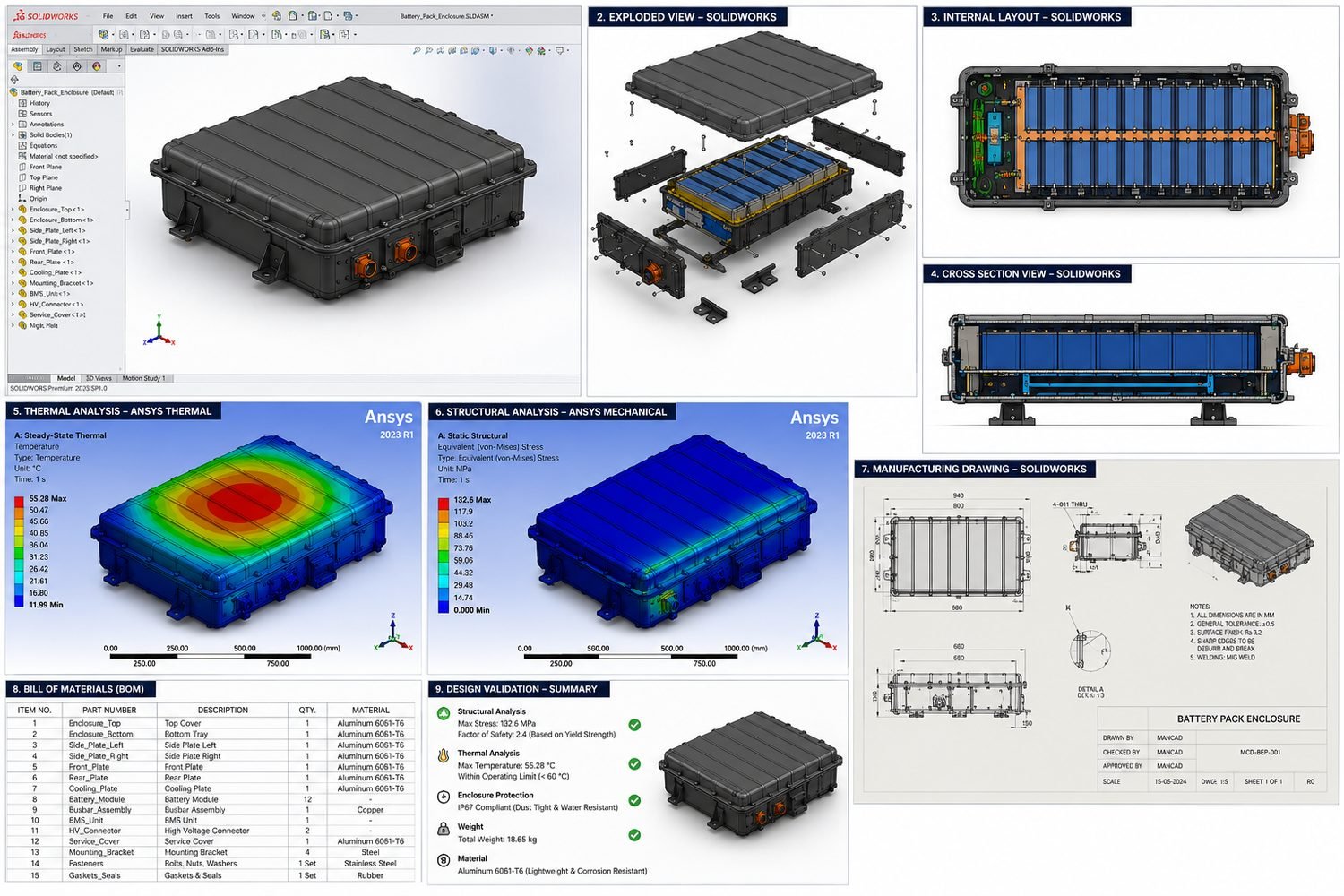
A 12 module enclosure was developed in SOLIDWORKS around cell packaging, sealing interfaces, fastener access and CNC machining constraints for 6061 T6 aluminum.
Work can include parametric parts, multi-part assemblies, mechanisms, product enclosures, sheet metal, molded components and manufacturing documentation when they fit the project scope. Each model is developed around function, interfaces, design intent and the intended production process.
Yes. Deliverables can include editable SLDPRT parts and structured SLDASM assemblies with purposeful mates, configurations, interference checks and motion relationships where needed. The assembly structure is planned so design changes, BOM updates and supplier reviews stay manageable.
Yes. Part and assembly drawings can include functional datums, dimensions, fits, tolerances, GD&T, materials, finishes, weld or bend notes, BOMs and revision blocks appropriate to the manufacturing and inspection plan.
Yes. SolidWorks CAD can be reviewed for machining, sheet metal, molding, assembly and inspection constraints before release. The goal is manufacturing-ready CAD that supports supplier quoting, prototyping, production handoff and practical design decisions.
Yes. Existing CAD, STEP files and broken assemblies can be inspected for geometry faults, missing references, mate conflicts and weak design intent. Useful geometry is retained where practical, then fragile areas are remodeled or repaired for a cleaner release package.
Yes. A project can begin from hand sketches, marked-up PDFs, photographs, measurements, legacy drawings or sample parts. Unknown dimensions and functional assumptions are documented for review before detailed CAD is released.
The agreed package can include SLDPRT, SLDASM and SLDDRW source files plus STEP, IGES, Parasolid, STL, DXF, DWG and PDF outputs. Release files are named and revision-controlled to prevent obsolete geometry reaching a supplier.
Yes. SolidWorks work can support concept CAD, product architecture, detailed mechanical design, DFM review, prototype updates, manufacturing drawings and supplier handoff. The scope can be phased so early decisions are reviewed before detailed modeling and documentation.
Send the available sketches or CAD, the product's function, key interfaces, target manufacturing process, materials, expected quantities and required outputs. If information is incomplete, the first milestone can be a focused design and risk review.
Cost and timing depend on design maturity, part and assembly count, manufacturing process, drawing requirements and validation scope. Simple part updates or drawing packages may take days, while product development and complex assemblies usually need staged reviews.
Yes. Remote SolidWorks design and mechanical CAD support is available to clients in the United States, Australia and worldwide. Reviews can be coordinated across time zones using controlled CAD, marked drawings, decision logs and supplier communication.
SolidWorks work often connects with Mechanical CAD Services, Product Design Engineering, Design for Manufacturing, Sheet Metal Design, Injection Molding Design, Manufacturing Drawings and GD&T and FEA Services.
Share the available CAD, sketch or manufacturing constraint. I will review the engineering risk, clarify the required SolidWorks design services and recommend a practical first milestone.