What Should a Manufacturer Ready CAD Package Include?
A clean supplier handoff is more than a 3D model. It gives the manufacturer enough controlled geometry, dimensions, materials, tolerances and revision context to quote and build the intended design without guessing.
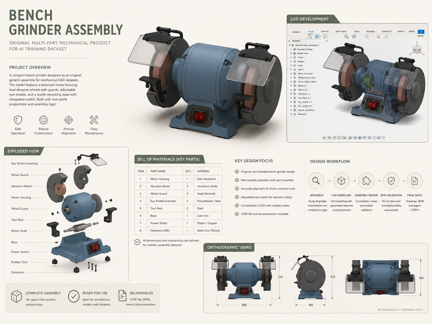
A 3D model can show the shape of a part while leaving critical manufacturing questions unanswered. Which material is required? Which faces must locate the assembly? What surface finish matters? Is a hole clearance, threaded or reamed? Which revision is approved? A supplier may be able to open the geometry and still be unable to quote or make it confidently.
The correct release package closes those gaps without burying the supplier in unnecessary files. Its contents depend on the manufacturing process, product maturity, contractual requirements and the supplier's own workflow. A CNC machine shop, sheet metal fabricator, injection molder and prototype bureau will not ask for exactly the same information.
A package is ready when a competent supplier can identify the approved design state, understand what must be controlled and raise focused manufacturing questions instead of reconstructing the designer's intent.
What “Manufacturer Ready CAD” Actually Means
The phrase describes a level of design definition, not a particular file extension. The distinction becomes clearer when the CAD is viewed across three stages.
Concept model
A concept model communicates an idea, overall form or packaging direction. It may be useful for discussion, rendering or early fit checks, but dimensions, interfaces, wall thicknesses and manufacturing details can still be provisional. It is normally too early to treat this geometry as an approved production definition.
Design development CAD
Development CAD resolves component interfaces, mechanisms, fastening, access, materials and likely manufacturing processes. The model may already look complete, yet decisions can remain open and revisions frequent. Prototype files often come from this stage because the objective is to learn rather than to freeze every production requirement.
Manufacturing ready CAD
Release CAD reflects the approved geometry and the intended process. Components and assemblies are internally consistent, critical requirements are defined, and the supporting documentation identifies what the supplier must hold. The model should also have passed an appropriate design and design for manufacturing review.
“Ready” does not mean every dimension is tightly toleranced or that every available export is included. It means the information is sufficient, controlled and appropriate for the selected supplier and process.
The Core Files a Manufacturer May Need
A release package is selected rather than copied from a universal checklist. Typical components include native CAD, neutral 3D geometry, drawings and process specific 2D data.
| Package component | What it communicates | When it is commonly useful |
|---|---|---|
| Native part and assembly files | Editable features, configurations, mates and design structure | Ongoing engineering collaboration or a supplier using the same CAD platform |
| STEP geometry | Stable neutral 3D part or assembly geometry | Quoting, CAM, tooling and cross platform exchange |
| Manufacturing drawings | Dimensions, tolerances, materials, finishes, notes and inspection intent | Machining, fabrication, molding control and formal release |
| DXF | Controlled 2D profiles | Laser, waterjet, plasma, routing or sheet metal flat pattern workflows |
| STL | Tessellated surface geometry | Many additive manufacturing workflows, not general production definition |
| Human readable drawings, specifications and release records | Quoting, purchasing, review and shop floor reference |
Assemblies may also require a bill of materials, approved purchased part references, finish specifications, inspection criteria or packaging notes. A simple prototype bracket may need only a STEP file, material note and a few controlled dimensions. A production assembly with many parts requires more discipline.
1. The 3D Part and Assembly Models
The released 3D geometry should represent the final approved shape for that revision. Suppressed features, placeholder components and alternative concepts should not be mixed into the supplier package unless they are intentionally documented.
For individual parts, check that manufacturing features are explicit and complete: holes, threads, fillets, chamfers, draft, bends, reliefs and interfaces should match the intended process. For assemblies, the structure should make the component relationships understandable. Referenced parts must resolve, and the assembly must not depend on missing local files.
Configurations are useful when they represent controlled product variants, manufacturing states or family members. They become risky when a supplier cannot tell which configuration is approved. Name the released state clearly and export only the required variants.
Revision consistency matters here as much as geometry. The part model, assembly and neutral export should describe the same design state. This is one reason structured mechanical CAD services focus on design intent and controlled assemblies rather than geometry alone.
2. Manufacturing Drawings
A 3D model defines nominal geometry, but a drawing can define how that geometry is to be made, verified and accepted. Drawings remain valuable whenever the supplier needs requirements that cannot be inferred safely from the model.
Depending on the part and process, a drawing may define:
- Functional and overall dimensions
- General and feature specific tolerances
- Material grade and condition
- Surface finish, coating, heat treatment or color
- Threads, inserts and hole callouts
- Critical interfaces and inspection characteristics
- Weld, bend, deburring or edge break notes
- Drawing scale, units, projection and revision status
The drawing should not duplicate every dimension simply because the software can generate it. It should communicate the requirements needed to manufacture and inspect the part. Overloaded drawings are harder to read and easier to misinterpret.
For formal supplier release, professionally prepared manufacturing drawings and GD&T connect nominal CAD geometry to material, tolerance, finish and inspection requirements.
3. GD&T and Critical Requirements
Tolerances should protect function. Tightening every dimension may appear safer, but it can increase machining time, inspection effort, scrap risk and cost without improving the product.
Start with what the part must do. A sealing face may need to remain flat relative to a gasket interface. A bearing bore may need controlled size and position relative to a mounting datum. A pattern of holes may need to assemble to another component. These functional relationships guide the datum structure and the appropriate controls.
Geometric dimensioning and tolerancing is most useful when it states those relationships more clearly than independent plus/minus dimensions. It should not be added decoratively. Datum features must be accessible and stable enough for manufacturing and inspection, and each control should have a reason.
Hold a tight tolerance only where fit, motion, sealing, alignment, strength or another verified function requires it. Allow the supplier reasonable freedom everywhere else.
The Planetary Gear Actuator is a relevant example of a precision machined assembly where the drawing package, interfaces and machining review matter together. The useful requirement is not “make everything precise”; it is “control the features that determine the actuator's fit and function.”
4. Design for Manufacturing Review
A model can be dimensionally correct and still be difficult, expensive or unreliable to manufacture. DFM checks whether the design suits the proposed process before the supplier is asked to solve avoidable design problems.
Common review questions include:
- Can cutting tools reach the required machined features without unnecessary setups?
- Are molded walls, ribs, bosses and draft appropriate for the material and tooling direction?
- Can sheet metal bends be formed with available tooling and sensible reliefs?
- Can fasteners be installed and serviced with real tools?
- Are there undercuts, trapped volumes or parting line problems?
- Could separate features be simplified without reducing function?
- Are tolerance and finish requirements realistic for the chosen process?
The objective is not to remove every difficult feature. Some demanding requirements are functionally necessary. The objective is to distinguish necessary complexity from accidental complexity and document the remaining risk.
A focused DFM review before supplier handoff is especially valuable before tooling, detailed quotations or production commitments make changes expensive.
5. File Formats and When to Use Them
No single format is universally best. The correct choice depends on how the recipient will use the information.
Native SolidWorks files
SLDPRT, SLDASM and SLDDRW preserve editable features, assembly relationships and drawing associations. They are useful when the client, engineering partner or supplier works in a compatible SolidWorks environment and needs controlled editability. Native files should be transferred with all required references, not as a broken assembly.
STEP
STEP is a widely used neutral exchange format for accurate 3D geometry. It is often appropriate for supplier quotation, CAM programming, tooling design and cross platform exchange. A STEP file usually does not carry the full editable feature history or all manufacturing requirements, so it may need to be paired with drawings or specifications.
STL
STL represents geometry as a triangular mesh. It is common in additive manufacturing, but it is not a strong general purpose master format for machining, drawing creation or controlled design exchange. Confirm the required resolution and units before export.
DXF
DXF is useful for 2D cutting profiles and sheet metal flat patterns. The released file should have the correct scale, units and geometry, with duplicate lines or construction geometry removed. Bend information and fabrication requirements may still need a drawing.
PDF is appropriate for issued drawings, specifications and review records because it is easy to open and preserves the intended page. It is not a substitute for usable 3D geometry when the supplier needs CAM, tooling or assembly data.
Projects built through SolidWorks design services can be handed over as an agreed combination of editable native files, neutral geometry and controlled documentation rather than an indiscriminate export folder.
6. Revision and Configuration Control
A technically complete package is still unsafe if the supplier cannot identify the approved revision. Drawings, CAD, BOM and process files must refer to the same design state.
Use a clear part number and revision convention. Record the revision in the drawing title block and file release record, and avoid sending multiple nearly identical folders named “final,” “final new” and “final latest.” If an updated part changes an assembly, determine whether the assembly, BOM, drawing and neutral exports also require a new revision.
For configured products, identify which variants are being quoted or built. Do not assume the active configuration that happened to be saved in the CAD file will be obvious to the recipient.
A concise transmittal note is often enough to remove ambiguity. It can list the released files, revision, purpose of issue, known open points and the person responsible for technical questions.
7. What a Good Supplier Handoff Looks Like
Imagine a multi part mechanical assembly being released for quotation. A clean folder might contain the following, adjusted for the actual manufacturing method:
- Final 3D CAD. Approved part geometry in the agreed native or neutral format.
- Assembly definition. The controlled top level assembly and required component references.
- Manufacturing drawings. Issued PDFs and, where agreed, native drawing files.
- Bill of materials. Part numbers, descriptions, quantities and relevant make or buy status.
- Process specific 2D files. DXFs or other profiles only where the supplier's workflow requires them.
- Material and finish requirements. Grade, condition, coating, treatment or approved alternatives.
- Revision record. A clear release revision and matching status across CAD, drawings and BOM.
- Special manufacturing notes. Assembly, welding, sealing, deburring or handling requirements that genuinely affect the build.
- Inspection requirements. Critical characteristics, reports or acceptance criteria where applicable.
The Countertop Convection Oven Assembly, for example, is described on the site as a 19 sheet manufacturing package with flat patterns, an insulated chamber, an extrusion frame, a door assembly and a 36 item BOM. That type of mixed assembly needs more than a single exported model because different components and suppliers depend on different release information.
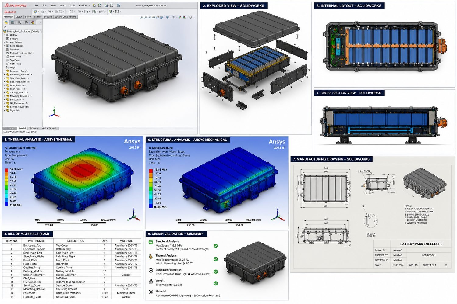
EV Battery Pack Enclosure
A machined aluminum enclosure developed around packaging, sealing, FEA and manufacturing documentation.
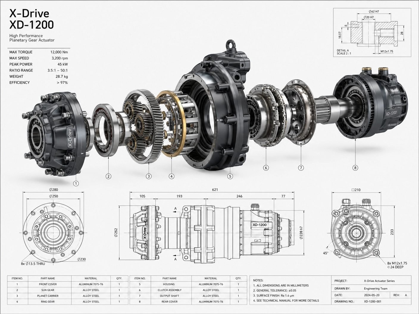
Planetary Gear Actuator
A machined power transmission assembly supported by an exploded view and manufacturing drawing package.
Common Mistakes Before Sending CAD to a Manufacturer
Sending the wrong revision
Outdated geometry can reach quoting or production when old exports remain beside the current release. Create a deliberate release package instead of forwarding the working directory.
Assuming the model explains every requirement
A STEP file will not tell the supplier which material, finish or tolerance is functionally important. Add the drawing or specification needed to communicate those requirements.
Mixing inconsistent files
If the drawing shows one hole pattern and the model shows another, the supplier must stop and ask, or may choose the wrong authority. Check that CAD, drawings, BOM and 2D exports were generated from the same approved state.
Tightening tolerances without a functional reason
Unnecessary precision can make a quote expensive and reduce the number of capable suppliers. Define functional limits, then allow the selected process to work efficiently.
Leaving material and finish undefined
“Aluminum” or “plastic” may not be enough. Grade, temper, resin, color, texture, coating or approved substitutes can affect performance, appearance, lead time and price.
Expecting the supplier to infer design intent
Suppliers contribute valuable manufacturing knowledge, but they should not have to decide the product's functional requirements. Identify critical interfaces and clearly separate approved requirements from open questions.
Final Manufacturer Ready CAD Checklist
Before issuing the package, confirm the following:
- The released 3D geometry matches the approved design.
- Every required part and assembly reference opens correctly.
- The intended configuration or variant is identified.
- Materials, finishes and special processes are defined where needed.
- Critical dimensions and tolerances are documented.
- GD&T controls functional relationships rather than decorating the drawing.
- The design has been reviewed for the selected manufacturing process.
- Native, STEP, STL, DXF and PDF files are included only where useful.
- Drawings, CAD, BOM and exports share the same revision state.
- Purchased components and approved supplier references are identifiable.
- Inspection or acceptance requirements are included where applicable.
- Obsolete and working files are excluded from the release folder.
- A transmittal note identifies the purpose of issue and any open questions.
This checklist should be adapted to the project. A prototype part does not need the release bureaucracy of a regulated production assembly, while an expensive tool or safety critical interface may require more control than this overview covers.
When You Need Engineering Help
Engineering support is useful when the geometry exists but the release state is uncertain, when supplier questions expose missing requirements, or when a prototype must be converted into controlled production CAD.
Depending on the gap, that support may involve rebuilding or organizing the model through Mechanical CAD Services, preparing editable parts and assemblies through SolidWorks Design Services, reviewing process risks through Design for Manufacturing, or creating the issued documentation through Manufacturing Drawings and GD&T Services.
The aim is not to add paperwork. It is to give the supplier a coherent technical definition and give the product team confidence about what was actually released.