Step
Engineering Objective
Define the decision, failure mode, acceptance criteria and evidence the analysis must provide.
Finite Element Analysis validates load cases, boundary conditions, stress, displacement, temperature and Factor of Safety before manufacturing. Structural Analysis, Thermal Analysis and SolidWorks Simulation help expose failure risks early, reduce prototype costs and support manufacturing-ready design decisions before tooling.
Problem: incorrect loads or unrealistic constraints can move stress to the wrong region. Consequence: the study may create a false pass or false failure. Correct approach: define credible operating, assembly, handling and exceptional load cases before solving.
Problem: poor boundary conditions, oversimplified contacts and a coarse mesh can hide stress concentrations or distort stiffness. Consequence: the reported peak may be mesh-dependent or physically misleading. Correct approach: refine critical regions and use mesh convergence checks to show the result is stable enough for the decision.
Problem: a polished stress plot without an engineering conclusion—or analysis performed after every dimension is frozen—is not validation. Consequence: teams receive images but no actionable decision. Correct approach: compare results with material limits, displacement criteria, Factor of Safety and thermal limits, document uncertainty, and recommend changes while the design can still evolve.
Each stage connects simulation choices to a product decision, review point or manufacturing outcome.
Define the decision, failure mode, acceptance criteria and evidence the analysis must provide.
Select structural, thermal, contact or buckling studies and develop representative load cases.
Prepare CAD, materials, contacts, boundary conditions and a mesh suited to the critical regions.
Review convergence, reactions and engineering calculations before interpreting stress, displacement or temperature.
Translate findings into practical design optimization and manufacturing-ready recommendations.
The example shows how simulation results support a documented design and manufacturing decision.
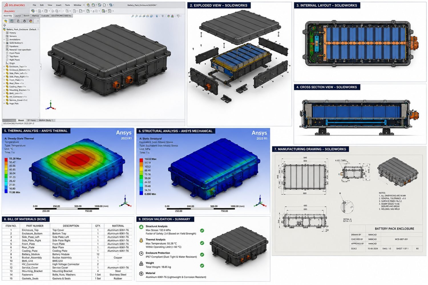
Objective: validate a 6061-T6 aluminum enclosure before manufacturing release. Packaging, material, sealing intent and production constraints shaped the model and acceptance criteria.
Strategy and findings: thermal and structural studies evaluated temperature, stress and load response. The reported 55.3°C peak temperature, 132.6 MPa peak stress and structural Factor of Safety of 2.4 were reviewed against the project criteria.
Engineering decision: the findings supported the enclosure design and informed the manufacturing drawing release, connecting simulation evidence with practical production documentation.
View projectFinite Element Analysis divides a component or assembly into a mesh and estimates its response to defined loads, constraints, contacts and temperatures. It supports decisions about stress, strain, displacement, temperature and Factor of Safety before manufacturing.
Use FEA while design decisions can still change—before expensive prototypes, machining, molds or production tooling. It is especially useful when load paths, stiffness, heat, contact, buckling or weight create risk.
Yes. SolidWorks Simulation is used for suitable structural and thermal studies, with the method selected around the engineering question, geometry, contacts, materials and required fidelity.
Yes, when the model represents the real engineering problem. Credible loads, realistic constraints, suitable material data, contact definitions, mesh convergence and independent checks matter more than the software name.
Yes. Thermal simulation can evaluate temperature distribution and heat flow under defined heat sources, conduction, convection and ambient conditions. Thermal results can also inform structural analysis when expansion matters.
Structural analysis evaluates stress, strain, displacement, stiffness, contact and Factor of Safety. Thermal analysis evaluates temperature and heat flow; its temperature field can be transferred when thermal expansion or thermal stress matters.
Yes. FEA can expose weak sections, excessive displacement, hot regions and inefficient material before a prototype is built, reducing avoidable iterations. Physical testing may still be needed for final validation.
Accuracy depends on assumptions and input quality. Representative material data, credible load cases, realistic boundary conditions, appropriate contacts, mesh refinement and convergence are essential.
Yes. Existing CAD, drawings, test observations or failed parts can be reviewed to evaluate likely load paths, stress concentrations, displacement, thermal behavior and corrective changes.
Yes. Simulation-driven design can compare thicknesses, ribs, cutouts, materials and load paths to remove unnecessary mass while maintaining defined stiffness, stress and safety targets.
Yes, when appropriate material and manufacturing assumptions are available. Plastic studies may need nonlinear behavior, creep, temperature, ribs, bosses, snap fits and contact effects considered.
Yes. Aluminum brackets, housings, frames and machined parts can be evaluated for stress, displacement, Factor of Safety, contact and thermal behavior using the correct alloy properties.
Yes. The simulation report can document the objective, assumptions, materials, boundary conditions, load cases, mesh strategy, results, limitations and engineering recommendations.
Yes. Existing studies can be reviewed for setup, constraints, contacts, mesh behavior and conclusions. Load cases can be developed from actual use, assembly, handling, transport and exceptional conditions.
Not always. FEA can reduce test iterations and make physical testing more focused, but safety-critical, regulated or highly uncertain products may still require prototype and production testing.
Yes—that is usually the best time. Findings can still influence wall thickness, ribs, supports, interfaces and material selection before machining, molding or fabrication changes become expensive.
Yes. An NDA can be signed before confidential product geometry, requirements, simulation files or supplier information are shared.
Combine engineering simulation with CAD development, DFM and production documentation only where the project requires it.
Share the CAD, operating conditions and known risks. The first milestone will focus on credible load cases, practical validation and manufacturing-ready recommendations.