DFM Checklist Before Sending a Product to a Manufacturer
A process-aware review of geometry, materials, tolerances, assembly and release files before a design reaches quotation, prototyping, tooling or production.
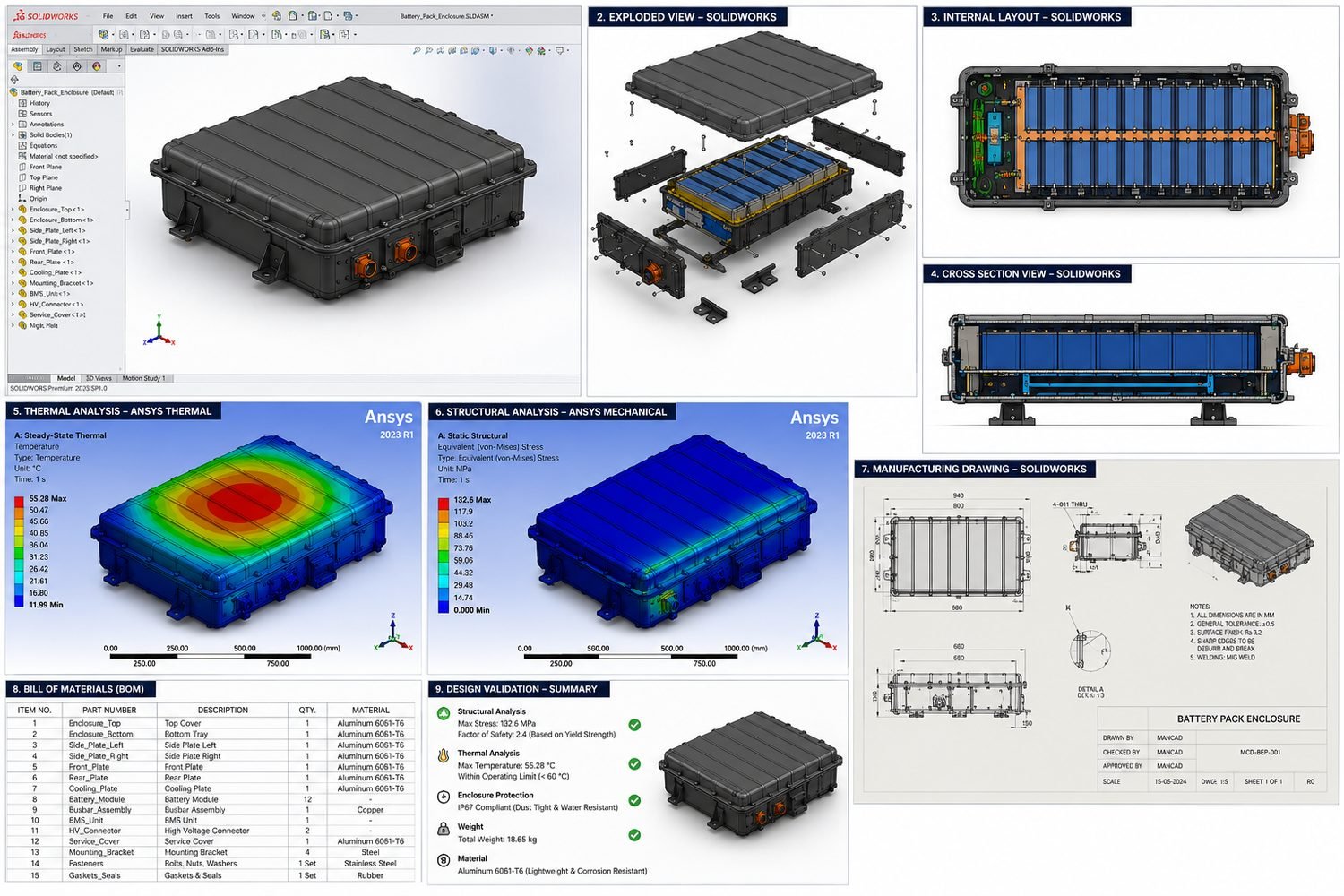
A CAD model can be geometrically complete and still be difficult, expensive or unreliable to manufacture. The shape may be closed, every component may fit on screen and the assembly may move correctly, yet the design can still create tool-access problems, molding defects, impractical bends, ambiguous tolerances or an awkward assembly sequence.
Design for Manufacturing identifies those problems before they become supplier questions, redesigns, tooling changes, delays or unnecessary cost. The objective is not to make every product simple. It is to ensure that each manufacturing challenge exists for a functional reason and is communicated clearly enough to quote, prototype, tool, fabricate, machine and produce.
Can the selected supplier make, finish, inspect and assemble this design repeatedly with a process that matches the product's function, volume, quality and cost targets?
What Does DFM Actually Check?
A DFM review considers the relationship between product geometry, material, manufacturing process, tolerances, assembly, finishing, inspection and production volume. A decision in one area often changes the others. Selecting a coating can affect masking and dimensional allowances. Tightening a bore tolerance can change machining and inspection plans. Moving a fastener can improve assembly access but weaken a molded boss or obstruct a cutting tool.
The exact checklist depends on the process. CNC machining is constrained by cutting-tool access, setups and workholding. Injection molding depends on material flow, wall behavior, draft, parting and ejection. Sheet metal depends on cutting, bend tooling, forming sequence and flat-pattern development. Additive manufacturing introduces build orientation, support and post-processing questions. The same product may combine several of these processes, so the review must follow each component through its intended route.
1. Confirm the Manufacturing Process
A design cannot be reviewed properly until the likely manufacturing process is understood. A pocket that is straightforward to print may be inaccessible to a milling cutter. A constant-thickness shell that suits molding may be inefficient to machine from billet. A sheet metal enclosure must be unfoldable and formable, not merely modeled as a thin solid.
Confirm whether each part is intended for CNC machining, injection molding, sheet metal fabrication, additive manufacturing, welded fabrication, casting or another appropriate process. For early prototypes, also decide whether the prototype process is testing geometry only or must represent the eventual production behavior. A printed plastic part can prove packaging and ergonomics, for example, without validating molded shrinkage, knit lines or tooling strategy.
The chosen process affects allowable geometry, tolerances, tooling, material availability, unit cost, setup cost and finish options. It also affects what a supplier needs to quote. A focused Design for Manufacturing review begins with this process context rather than treating manufacturability as a generic property of the CAD model.
2. Check Material and Finish Requirements
State the material with enough precision for the product and sourcing stage. “Aluminum,” “steel” or “plastic” may be too vague when grade, condition or resin choice affects strength, corrosion resistance, machinability, molding behavior, appearance or compliance. At an early quotation stage, approved alternatives can be identified deliberately instead of being left to assumption.
Define required surface finish, coating, anodizing, plating, painting or heat treatment where these affect performance or appearance. Consider which faces are cosmetic, conductive, sealing, sliding or dimensionally controlled after finishing. Coating thickness, masking and processing sequence may matter at fits, threads, grounding points and sealing interfaces.
Vague requirements invite supplier questions and inconsistent quotes. Over-specification creates a different problem: it can restrict materials or finishes without functional benefit. Document the outcome the part must achieve and add process detail where it is necessary to control that outcome.
3. Review Geometry for Manufacturability
Review the shape through the eyes of the actual process. Look for inaccessible features, unnecessarily deep cavities, thin or fragile sections, sharp internal corners, difficult tool access and complexity that does not protect a product requirement.
For machining, a deep narrow pocket may require a long, less-rigid tool and slower cutting. A sharp internal corner may be impossible with a rotating cutter unless another process is used. For molding, thick isolated masses can cool differently from surrounding walls, while trapped undercuts can prevent a simple tool from opening. For additive manufacturing, enclosed volumes or downward-facing features can trap powder or make support material difficult to remove.
Geometry should not be simplified blindly. A sealing land, bearing seat, controlled airflow path or ergonomic surface may justify extra work. The review should distinguish function-driven complexity from features that remain only because of an earlier concept or convenient modeling method.
4. Review Wall Thickness, Ribs and Bosses
This check is especially important for plastic and injection-molded components. Excessively thin walls may be difficult to fill or may lack required stiffness. Excessively thick sections can increase material use, cooling time and the risk of visible sink or internal variation. Abrupt transitions can produce uneven behavior even when the overall wall thickness appears reasonable.
Ribs can add stiffness without turning an entire panel into a thick section, while bosses can locate fasteners, inserts or mating parts. Their proportions, support and connection to nearby walls must be considered together. A boss that is too isolated may be weak; a heavy boss joined directly to a cosmetic wall can create a sink-risk area. Transitions should support material flow and structural load without creating unnecessary mass.
There is no universal wall, rib or boss value. Appropriate proportions depend on resin, molding process, part geometry, tool design, application, finish expectations and supplier capability. These features should be reviewed with the material and tool direction in mind through an appropriate Injection Molding Design service.
5. Check Draft and Parting Strategy for Molded Parts
Draft allows a molded part to release from the tool without excessive drag, scuffing or ejection force. The required amount is not one universal angle: it depends on material, depth, texture, surface requirement and tooling guidance. The important early decision is to establish the primary pull direction and review relevant faces consistently.
Parting direction determines where the core and cavity separate, where the parting line appears and which features become undercuts. An undercut may be justified, but it can require slides, lifters, collapsible features or a different assembly strategy, increasing tooling complexity and maintenance.
Ejector access also matters. The part needs suitable areas for ejection without damaging cosmetic or critical surfaces. Draft, parting, shutoffs, undercuts and ejection should be considered as one molding strategy, not as isolated checks added after the exterior styling is complete. This is a core part of injection molding design.
6. Check CNC Machining Access and Tooling
For machined components, confirm that cutting tools can reach the required features with sensible tool length, diameter and orientation. Review internal corner geometry, deep pockets, narrow slots, small features and holes that enter at difficult angles. Consider how the part can be held and whether critical surfaces remain accessible after each setup.
Every additional orientation can add setup, probing and handling time. A feature that forces a special tool or an extra setup may still be necessary, but its cost should be understood. Small changes to feature direction, corner radius, stock shape or datum location can sometimes reduce machining time without changing function.
Tolerance is part of the machining strategy. A tight relationship between features machined in different setups can be harder to achieve and inspect than the same relationship created from one orientation. Mechanical CAD Services can develop process-aware geometry, while a DFM review can identify access, setup and specification risks before quotation.
7. Check Sheet Metal Manufacturability
Sheet metal design should reflect the actual cutting and forming route. Confirm material and thickness, bend locations, bend access, bend radii, relief strategy and the relationship between holes or cutouts and nearby bends. Features placed in a deformation zone can distort during forming, while a bend that looks valid in CAD may be inaccessible to the planned tooling.
Review the flat pattern for laser-cut geometry, duplicate or overlapping edges, small slivers and features that may not cut cleanly. Then consider the forming sequence: a flange formed early can block tooling required for a later bend. Welds, fasteners, inserts and finishing can introduce additional access and distortion questions.
Bend allowances, radii and tooling depend on material, thickness, equipment and the fabricator's process. A production model should therefore be developed and verified through Sheet Metal Design Services with the intended supplier route in mind.
8. Review Tolerances and GD&T
“Make everything extremely precise” is not a useful release strategy. The better instruction is to specify the precision required for function. Identify the dimensions and geometric relationships that control fit, motion, sealing, alignment, safety or interchangeability, then allow reasonable manufacturing variation elsewhere.
Review critical dimensions, functional tolerances, datum strategy and inspection requirements together. Datums should represent stable, accessible features that meaningfully locate the part for manufacturing, assembly or verification. GD&T is valuable when it communicates a functional relationship more clearly than independent plus/minus dimensions; it should not be added decoratively.
Unnecessarily tight tolerances can increase process time, scrap exposure and inspection cost. They can also reduce the number of capable suppliers. Issued Manufacturing Drawings and GD&T Services should communicate what must be controlled and how that control relates to product function.
9. Check Fasteners, Threads and Assembly Access
A part can be manufacturable by itself and still create problems in assembly. Verify that a real screwdriver, hex key, socket, rivet tool, press or welding torch can reach each operation. Check tool clearance through the full installation path, not only the final fastener location.
Review threaded features, engagement, inserts and nearby wall or edge conditions with the selected material and process in mind. Confirm that captive hardware, loose nuts and washers can be placed and retained. Where inserts are used in plastics or sheet metal, consider installation access and the loads transferred into the surrounding structure.
Walk through the assembly sequence. Components must enter in a feasible order without interference, inaccessible connectors or hidden fasteners that become trapped by later parts. Also consider serviceability: if a wear component, battery or seal must be replaced, the intended maintenance path should not require destructive disassembly.
10. Check Interfaces and Critical Features
Interfaces deserve extra attention because errors propagate across components. Review mating faces, hole patterns, shafts, bearings, seals, mounting points, connectors and enclosure openings. Confirm the nominal geometry, tolerance relationship, assembly direction and surrounding clearance.
For bearings and shafts, the fit must reflect load, motion, material and assembly method. For seals, the groove, mating surface, compression intent, finish and fastening strategy work as a system. For connectors and enclosure interfaces, verify keep-out zones, cable bend space, panel thickness, tool access and sealing where required.
Use the assembly, not isolated part files, to review these relationships. The portfolio's Rugged Sensor Enclosure, for example, is documented with a removable lid, an O-ring groove, controlled mating surfaces and IP67 sealing intent—features whose behavior depends on the interface rather than either part alone.
11. Review the Manufacturing Drawing Package
The 3D model establishes nominal geometry, but it may not communicate every manufacturing requirement. A supplier may still need dimensions, tolerances, material, finish, notes, critical characteristics, revision status and inspection requirements.
Drawings should focus on information needed to make and verify the part. They should identify units and projection, distinguish reference information from controlled requirements and avoid contradictions with the model. Critical characteristics should be visible and traceable without turning every dimension into a special requirement.
For complex or mixed-process assemblies, the package may include part drawings, assembly drawings, a BOM, flat patterns and process-specific notes. The Countertop Convection Oven Assembly is described in the portfolio as a 19-sheet manufacturing package with flat patterns and a 36-item BOM, illustrating why one 3D export may not be enough. Manufacturing Drawings and GD&T Services connect the CAD definition to supplier and inspection requirements.
12. Check Revision and File Consistency
One of the easiest ways to create manufacturing problems is to send inconsistent files. Confirm that the native CAD model, drawing, BOM, DXF, STEP, PDF and revision information all describe the same approved design where each format applies.
Remove obsolete exports from the release folder. Check that assembly references resolve, drawing views reflect current geometry, flat patterns were regenerated and the BOM matches the assembly state. Use clear part numbers and revisions instead of ambiguous filenames such as “final latest.”
A short transmittal can list the purpose of issue, released files, revision and known open questions. For a fuller handoff review, see What Should a Manufacturer Ready CAD Package Include?
The Final DFM Checklist
Use the applicable items below. A molded housing, machined bracket and formed sheet metal panel will not require the same checks, and prototype needs may differ from production release.
- Geometry suits the selected manufacturing process.
- Critical features are accessible to the required tool, mold action or post-process.
- Mating interfaces and functional clearances have been reviewed in the assembly.
- Assembly and service access have been checked with real tools and components.
- Complex features have a documented functional reason.
- Material and grade or resin are specified where required.
- Finish, color, coating or texture is defined where required.
- Heat treatment, plating, anodizing, painting or masking is documented where applicable.
- Finish effects at fits, threads, seals and grounding points have been considered.
- Tool access, workholding and likely setups have been reviewed for machined parts.
- Wall transitions, ribs, bosses, draft, parting and ejection have been reviewed for molded parts.
- Bends, reliefs, hole proximity, flat pattern and forming sequence have been reviewed for sheet metal parts.
- Build orientation, support removal and post-processing have been reviewed for additive parts.
- Supplier-specific constraints are identified for confirmation rather than assumed.
- Critical dimensions and functional tolerances are identified.
- Unnecessarily tight tolerances have been removed.
- Datum strategy and GD&T communicate functional relationships where appropriate.
- Material, finish, notes and inspection requirements are documented.
- The model and drawing do not contradict each other.
- The CAD revision is approved for the intended issue.
- Drawing, BOM and export revisions match the CAD.
- Required native, STEP, DXF and PDF files are included where applicable.
- Obsolete and working files are excluded.
- Likely supplier questions and open engineering decisions are recorded.
This checklist is a decision aid, not a substitute for process-specific supplier input. When material, machine, tool or production volume changes, repeat the affected checks.
When Should a DFM Review Happen?
DFM should not wait until the design is considered finished. The most useful review points correspond to decisions that are about to become more expensive to change.
Early concept review
Confirm likely processes, material families, part count and major assembly strategy before details accumulate around an unsuitable concept.
Detailed design review
Review feature geometry, access, interfaces, tolerances and process-specific requirements while the CAD is mature enough to evaluate but still practical to revise.
Pre-prototype review
Decide what the prototype must prove and whether its manufacturing method represents production behavior. Remove preventable problems that would otherwise obscure the test result.
Pre-tooling review
Resolve molding, forming, casting or fixture questions before committing to expensive tooling. Supplier feedback is particularly valuable here because equipment and tool standards vary.
Pre-production review
Confirm released revisions, drawings, inspection criteria, assembly sequence and changes learned from prototypes or pilot builds. At this stage the review should verify a controlled definition, not reopen the product without evidence.
Earlier feedback generally offers more design freedom and lowers the cost of correction. Later reviews remain necessary, but their purpose shifts from shaping the concept to controlling the release.
When You Need a DFM Review
A review is useful when the CAD looks complete but the manufacturing route is uncertain, when quotation feedback is inconsistent, when supplier questions keep exposing missing decisions, or before committing to prototypes, fixtures or production tooling.
Design for Manufacturing Services can provide a focused, process-aware assessment of geometry, material, tolerances, assembly and release readiness. Where the gap is broader, the review can connect naturally to Mechanical CAD, SolidWorks Design, Injection Molding Design, Sheet Metal Design or Manufacturing Drawings and GD&T without adding work that the product does not need.