Manufacturing Drawing Package Checklist for Supplier RFQs
A practical guide to the drawings, CAD models, specifications, tolerances and revision information suppliers need to quote, manufacture and inspect a product with fewer assumptions.
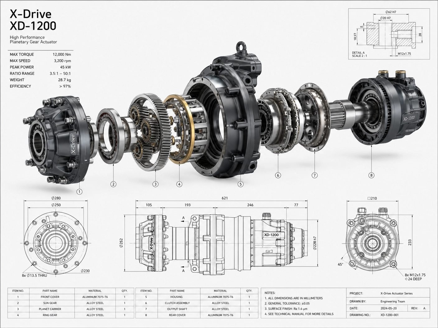
Manufacturers need more than recognizable geometry. They need a controlled definition of the part or assembly: what it is made from, which features matter, how much variation is acceptable, what finish applies and which revision they are being asked to quote.
A 3D CAD model is valuable, but it may not show functional tolerances, datum relationships, thread details, finish boundaries, inspection expectations or release status. When those requirements are unclear, suppliers must ask questions, price uncertainty into the quote or make assumptions that can lead to variation and delay.
A good RFQ package communicates enough design and manufacturing intent for suppliers to understand the work, prepare comparable quotations and identify genuine process questions. It is not simply every file exported from CAD.
Can the supplier identify the current design, understand what affects function and cost, choose a suitable manufacturing route, and see how the finished parts will be accepted?
What Is a Manufacturing Drawing Package?
A manufacturing drawing package is the controlled set of engineering information issued for quotation or production. Depending on the product and sourcing stage, it can include engineering drawings, 3D CAD models, bills of materials, material specifications, finish requirements, manufacturing notes, inspection requirements, process-specific 2D files and revision information.
The exact contents depend on the geometry, process, supplier, product maturity and purpose of issue. A single machined spacer may need one drawing and one model. A mixed-process assembly may require detail drawings, an assembly drawing, a BOM, neutral models, flat patterns and specifications. Not every package needs every possible document.
The package should distinguish controlled requirements from supporting information. A PDF drawing may define dimensions and notes while a STEP file supplies nominal geometry for CAM. If both are provided, they must describe the same design state and their roles should be clear.
1. Part and Assembly Drawings
Individual part drawings define the requirements that apply to one manufactured item. They commonly show the views needed to understand the part, dimensions not adequately conveyed by the model, material, finish, tolerances and notes. Section views are useful when internal features would otherwise be hidden; enlarged detail views can clarify small interfaces, grooves or edge conditions.
Assembly drawings explain how components relate. They can show orientation, item identification, fastening, alignment, assembly sequence or overall interface dimensions. Detail drawings remain appropriate when a supplier must manufacture and inspect individual components rather than treat the assembly as a single purchased item.
A drawing is still useful when a 3D model is included because it records requirements that nominal geometry alone cannot communicate. The drawing should add manufacturing and inspection meaning, not duplicate every model edge with a dimension.
2. Dimensions and Critical Features
Dimensions should communicate what matters to function and supplier planning. Typical needs include overall size, interface locations, hole patterns, mating features, envelope limits and dimensions needed to verify or manufacture features that are not fully controlled by the model.
Identify critical features because their relationships often determine fit, alignment, sealing, motion or assembly. A mounting pattern may need to align with another component; a bore may locate a bearing; a sealing land may control enclosure performance. These requirements deserve more attention than nonfunctional edge locations.
Do not add dimensions merely to fill the drawing. Redundant or chained dimensions can conflict, create closed tolerance loops or make design changes harder to control. The objective is an unambiguous functional definition, not the greatest possible number of annotations.
3. Tolerances
General tolerances establish reasonable defaults for applicable dimensions, while individual tolerances control features that need different limits. Functional tolerances should reflect what the part must do: fit another component, maintain clearance, seal, align, rotate or remain interchangeable.
Unspecified tolerances create ambiguity because a supplier cannot confidently choose a process or estimate inspection effort. Unnecessarily tight tolerances create the opposite problem. They can require slower processes, additional setups, special measurement, more capable equipment or greater scrap exposure, increasing cost without improving the product.
For an RFQ, identify the relationships that affect process capability and price. Where the tolerance scheme needs development or review, Manufacturing Drawings & GD&T Services can connect the drawing requirements to function, manufacture and inspection.
4. GD&T Where It Actually Adds Value
Geometric dimensioning and tolerancing can express how a feature's form, orientation or location relates to product function. A datum framework gives manufacturing and inspection a common way to establish the part. Position can control a hole pattern relative to that framework; flatness can control a surface independently; perpendicularity and parallelism can control orientation; profile can manage complex surfaces; and runout can be relevant to rotating features.
The value is clarity, not symbol count. Datums should represent meaningful, stable and accessible locating features. Controls should protect actual assembly or performance requirements and be measurable with an appropriate method. Decorative or excessively restrictive GD&T can confuse suppliers and inflate inspection effort.
Use GD&T when it communicates the required geometric relationship more accurately than simple plus/minus dimensions. The site's GD&T service focuses on functional datum strategies and controlled requirements rather than adding notation everywhere.
5. Material Specification
State the material with enough detail for the supplier to source, quote and process it correctly. Depending on the application, this may include material family, grade, specification, condition, hardness or required treatment. If substitutions are acceptable, define whether they require approval instead of leaving equivalence to assumption.
The appropriate level of detail varies. Alloy condition can affect machining and strength; sheet grade can affect forming; resin selection can affect molding, appearance and performance. Heat treatment may change dimensions or introduce a later process step. Early RFQs may deliberately request options, while a released production drawing may need a fixed requirement.
Avoid inventing precision that the design does not need. Material requirements should be supported by function, environment, process and sourcing strategy.
6. Surface Finish and Finishing Requirements
Communicate surface texture and post-processing where they affect function, durability, appearance or quotation. Relevant requirements can include anodizing, plating, painting, powder coating, polishing, blasting or another project-specific finish. Identify color, appearance, masking or controlled areas when they matter.
Finish can affect fits, sealing faces, threads, electrical contact, cosmetic surfaces and dimensional inspection. A supplier may need to know whether dimensions apply before or after coating, which faces must remain uncoated and whether appearance expectations apply to all surfaces or only designated ones.
Do not prescribe a finish solely because it is familiar. Specify the result required by the product and provide enough detail for suppliers to quote the same scope.
7. Threads, Holes, Inserts and Fasteners
Hole information should clearly distinguish clearance holes, tapped holes, precision bores and other feature types. Communicate relevant size, location, depth and any counterbore or countersink. Thread callouts need to identify the intended thread and applicable depth or through condition without forcing the supplier to infer it from nominal model geometry.
Where the design uses threaded inserts, captive hardware or process-installed fasteners, identify the component and installation requirement. Purchased fasteners should be defined well enough to quote and assemble, normally through the drawing or BOM as appropriate.
Ambiguous thread depth, incomplete counterbore information or conflicting modeled and annotated holes are frequent sources of supplier questions. Check these features in the model, drawing and assembly context before release.
8. Assembly Drawings and BOM
An assembly drawing and bill of materials become important when the supplier must understand component relationships, procure items, manufacture several parts or deliver an assembled unit. Item numbers should connect drawing balloons to clear component identification. The BOM can distinguish purchased and manufactured components and state quantities for the assembly.
The assembly definition should make orientation and interfaces understandable without requiring the supplier to reverse-engineer the CAD tree. Exploded views, sections or focused details can help when they clarify build relationships, but they should not replace necessary specifications or part-level controls.
A single-part RFQ does not need an artificial assembly BOM. Use one where component identification, quantities and purchasing scope genuinely require it. The portfolio's Countertop Convection Oven Assembly, for example, is documented as a 19-sheet package with flat patterns and a 36-item BOM—an appropriate level of structure for a multi-part fabricated product.
9. Manufacturing-Specific Files
Different suppliers use different production workflows, so ask which file formats they prefer and decide which documents remain authoritative.
CNC machining
A neutral STEP model is commonly useful for quoting and CAM, while a drawing controls tolerances, datums, threads, finishes and inspection requirements. Native CAD may be appropriate for close engineering collaboration when the supplier uses a compatible system, but it should not be the only record of release requirements.
Sheet metal and fabrication
Suppliers may request a formed 3D model, drawing, flat pattern and DXF as appropriate. Define material and thickness, bends, formed dimensions, welds, hardware and finish. Flat-pattern assumptions and bend data should align with the intended fabricator's tooling and process. Sheet Metal Design Services can prepare formed models, flat patterns and fabrication documentation together.
Injection molding
Molders typically need a usable 3D model plus material and relevant drawing requirements. Tooling-related information may include expected surfaces, parting intent, critical interfaces or other requirements appropriate to the sourcing stage. Mold strategy, shrinkage treatment and supplier-specific tooling details should be coordinated rather than guessed. See Injection Molding Design Services for process-aware part development.
Other processes and mixed assemblies
Welded fabrication, casting, additive manufacturing and other processes may require different supporting data, notes or specifications. A mixed assembly may need separate packages for machined, formed, molded and purchased components. Send files that support the actual supplier scope, not a generic export folder.
10. Revision Control
Every supplier should be able to identify which design state is current. Use the established revision identifier and, where the document system uses them, the revision date, change description and document status. A preliminary RFQ, prototype release and production release may carry different approval meaning even if the geometry appears similar.
The CAD model, drawing, BOM, STEP, DXF and other exports must be consistent. Remove superseded files from the issue package and avoid filenames such as “final-new” that cannot be traced to a controlled revision. If one file is supporting information rather than the release authority, say so.
For a broader review of model formats, references and release organization, read What Should a Manufacturer Ready CAD Package Include?
11. Inspection and Quality Requirements
Identify critical characteristics and inspection expectations where they are necessary to demonstrate functional compliance. This may include measurement of selected dimensions or geometric controls, a first article review, material or finish documentation, or other records required by the project.
Inspection requirements should match risk and function. Demanding a comprehensive report for every feature can add cost without improving confidence, while failing to identify a critical interface can allow an important problem to reach assembly. Consider whether the feature is accessible and whether the intended measurement method can verify the stated control.
Do not assume customer-specific standards or documentation. State the actual deliverables required for the RFQ and invite suppliers to identify measurement limitations or propose an appropriate method.
12. Notes and Special Requirements
Drawing notes capture requirements that do not belong conveniently in a dimension. Depending on the part, they can address deburring, treatment of sharp edges, finish, cleanliness, assembly, marking, special handling or packaging.
Notes should be specific enough to act on and limited to the applicable scope. A general instruction copied from another project can conflict with material, process or geometry. Distinguish requirements from preferences, and avoid asking the supplier to infer what “good workmanship” means for a critical feature.
Review the notes together with the model and other annotations. A finish note should agree with the title block and BOM; an assembly note should use the same component identification as the assembly drawing.
13. The Supplier RFQ Checklist
Use the items that apply to the part, process and quotation stage. A single machined component, molded housing and multi-part fabricated assembly will not need identical documents.
- Part drawings are included for components that need controlled requirements.
- Assembly drawings are included where relationships, fastening or supply scope must be understood.
- Current CAD models are included in the formats needed for quotation.
- Required 2D production files, such as applicable DXFs or flat patterns, are included.
- A BOM is included where component identity, quantity or purchasing scope requires it.
- Critical dimensions and interfaces are identified.
- Functional tolerances are defined and unnecessarily tight limits have been reviewed.
- GD&T is used where it clarifies form, orientation or location requirements.
- Datums are meaningful and accessible where a datum framework is required.
- Material, condition or treatment is specified to the level needed for the RFQ.
- Surface and finishing requirements are clear where applicable.
- The intended or likely manufacturing process is identified.
- Special manufacturing requirements are documented rather than implied.
- Threads, holes, inserts and installed hardware are clearly defined.
- Critical mating, sealing, motion or mounting interfaces are visible.
- Process-specific files match the controlled geometry.
- The drawing revision and issue status are correct.
- CAD and neutral exports match the drawing revision.
- The BOM revision matches the assembly where applicable.
- Obsolete and working files have been excluded.
- The complete RFQ package is internally consistent.
- Critical characteristics are identified where required.
- Inspection expectations reflect actual functional risk.
- First article or measurement documentation is identified where applicable.
- Material, finish or other supporting documentation is requested only where needed.
Common Mistakes in RFQ Drawing Packages
- Outdated drawings: the supplier quotes a superseded design because old files remain in the package.
- Mismatched revisions: the drawing, CAD model and BOM describe different states of the product.
- Missing material or finish: suppliers price different assumptions, making quotations difficult to compare.
- Unclear tolerances: critical limits are absent, or defaults and individual controls conflict.
- Over-tolerancing: noncritical features carry precision that increases process and inspection cost.
- Missing interfaces: mating patterns, sealing surfaces or assembly clearances are not visibly controlled.
- Ambiguous threads: thread type, depth, insert or related counterbore information is incomplete.
- Missing process files: a fabricator receives no usable flat profile, or a machine shop receives geometry without controlled requirements.
- Unstated design intent: the supplier is expected to decide which surfaces, dimensions or characteristics matter.
These problems do more than generate emails. They can cause suppliers to include different scopes and risk allowances, so the lowest quote may not represent the same product definition as the highest.
How Detailed Should a Drawing Be?
A useful drawing sits between two failure modes. Too little information forces suppliers to infer material, finish, tolerance or functional intent. Too much information can create contradictions, duplicate model definition and control features that have no effect on the product.
Add the information required to quote, manufacture, inspect and assemble the item appropriately. Give greater definition to critical interfaces and special processes. Let general requirements cover ordinary features when that approach is compatible with the drawing system and supplier workflow.
“More dimensions” is not the same as “better definition.” The better drawing makes requirements easy to find, relates controls to function and avoids unnecessary constraints. A Design for Manufacturing review can also reveal where a drawing issue is actually a geometry, process or assembly decision that should be resolved in CAD first.
Before You Send the RFQ
- Open the issue folder as if you were the supplier and confirm the scope is obvious.
- Check that every file opens and that drawing views, models and BOMs show the same revision.
- Confirm material, finish, quantity and intended process are stated where needed for pricing.
- Review critical interfaces, tolerances, threads and inspection expectations.
- Remove obsolete exports, duplicate files and uncontrolled working data.
- List approved alternatives, open questions and supplier-requested formats.
- Include a clear contact path for technical clarification.
If supplier quotes differ substantially, compare their assumptions before comparing price. One supplier may have included finishing, inspection or purchased components that another has excluded.
When You Need Manufacturing Drawings or GD&T Support
Support is useful when the CAD is mature but the release requirements are incomplete, supplier questions keep exposing ambiguity, critical interfaces need a functional tolerance strategy, or the model and drawing package have diverged during revision.
Manufacturing Drawings & GD&T Services can develop or review part drawings, assembly documentation, datums, tolerances, materials, finishes and revision consistency for the intended supplier handoff. Where the design itself needs work, that support can connect to Mechanical CAD Services, SolidWorks Design Services or Design for Manufacturing without expanding the scope beyond what the product requires.