Design for Injection Molding: 7 Common CAD Mistakes That Increase Manufacturing Costs
A plastic part can look complete in CAD while its wall thickness, draft, ribs, bosses, undercuts or tolerances still make tooling and production more difficult.
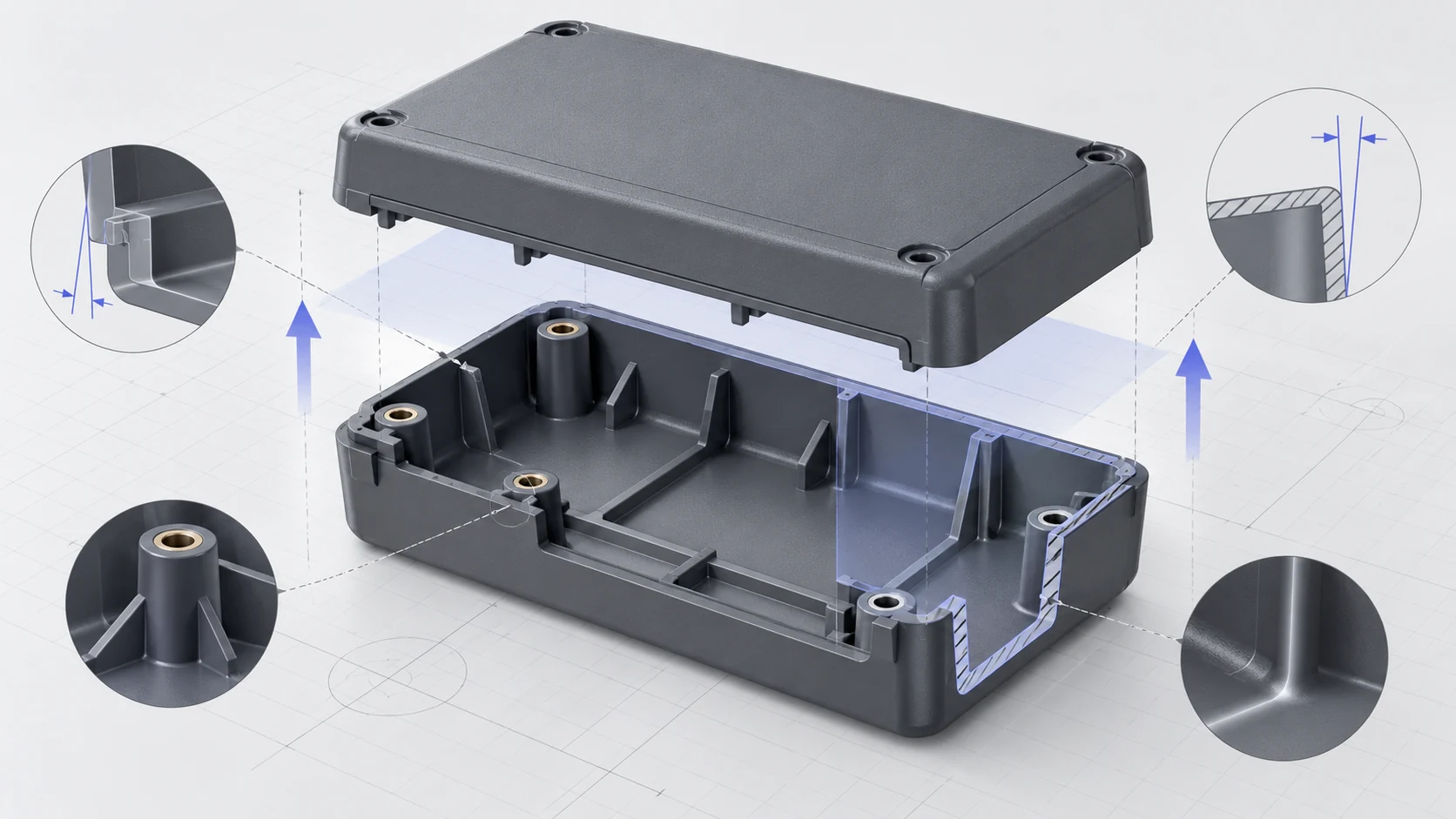
A plastic component can look complete in CAD and still be difficult or expensive to manufacture. The geometry must work not only as a digital shape, but also with mold opening, molten-material flow, cooling, ejection, dimensional stability and the requirements of the final assembly.
Design for manufacturing (DFM) is the process of reviewing those relationships while the design can still change. For injection-molded parts, an early DFM review helps identify geometry that may require complicated tooling, create uneven cooling, resist ejection or make consistent assembly harder after production starts.
The appropriate wall thickness, draft, rib and boss proportions, tolerances and tooling strategy depend on the selected resin, component geometry, mold construction, production requirements and manufacturing supplier. The guidance below supports engineering decisions; it does not replace resin data, mold-flow analysis when justified, or a toolmaker's review.
Why Injection Molding DFM Matters
Decisions made during concept development influence more than the appearance of the final part. They affect how many mold actions are needed, whether a feature can be machined and maintained, how the cavity fills, where the component shrinks as it cools, and how reliably it can be ejected.
These decisions also affect cycle time, dimensional consistency and the amount of inspection or process control required. A thick region may need more cooling time. An avoidable side opening may require a slide. An unjustified tight tolerance may restrict the acceptable process window. Each issue can add cost or uncertainty even when the CAD model looks visually attractive.
A production-ready design therefore connects function and appearance to a credible manufacturing method. Reviewing injection molding CAD early allows the product team and supplier to resolve assumptions before tooling geometry becomes difficult to change.
1. Designing Uneven or Excessively Thick Walls
Wall thickness has a strong influence on filling and cooling. When neighboring regions have substantially different thicknesses, they can cool and shrink at different rates. That differential behavior may show up as visible distortion, dimensional variation or internal stress.
Thick sections retain heat longer and may contribute to sink marks—local depressions that appear as the interior continues to shrink after the surface has begun to solidify. They can also increase the risk of internal voids and extend the cooling portion of the molding cycle. Abrupt transitions between thick and thin material can make these effects harder to manage and can interrupt a smooth flow path.
A useful starting principle is to establish a consistent nominal wall and use gradual transitions where thickness must change. Stiffness is often better developed with appropriate ribs, curvature or section shape than by adding solid mass. The nominal value and any permitted transitions must still be checked against the chosen resin, flow length, component geometry and supplier capability.
Practical example: a heavy enclosure corner
Consider a plastic enclosure with a thick corner created by the intersection of two walls, an exterior radius and a nearby screw boss. From the outside, the corner may look simple and robust. In section, however, those features can combine into a large concentration of plastic that cools more slowly than the surrounding shell.
Coring the corner, separating the boss from the exterior wall where practical, and connecting it with carefully proportioned support ribs can reduce the material concentration while preserving the load path. The final arrangement should be reviewed for fastening loads, tool access, flow and the cosmetic requirement on the opposite face.
2. Forgetting Draft Angles
Draft is a deliberate taper applied to a surface that runs in the direction of mold release. As the mold opens and the part moves off a core or out of a cavity, the taper creates clearance. Without sufficient draft, a large area can continue rubbing against the tool during ejection.
Insufficient draft may contribute to sticking, drag marks, scuffing, surface damage or higher ejection forces. Deep walls and pockets deserve particular attention because a small angular change creates more release clearance over a longer draw depth. Internal surfaces, ribs and bosses need review as well as the visible exterior.
There is no single draft angle that is correct for every part. Texture usually needs more release allowance than a smooth polished surface; material behavior, surface finish, feature depth and the proposed ejection strategy also matter. Draft should therefore be considered when the base features are created in CAD, not applied as a last operation after interfaces and exterior styling have been fixed.
Establish the likely mold-opening direction early, then use draft analysis to locate neutral or reverse faces. Confirm the final direction, surface specification and draft requirements with the tooling supplier.
3. Using Poorly Designed Ribs
Ribs improve stiffness by increasing the effective section depth without turning an entire panel into a thick solid section. They can also support bosses, guide assembly and help control local deflection. Their value depends on the load path and on geometry that can be filled, cooled and released reliably.
An excessively thick rib base can create a heavy intersection with the nominal wall. That extra material may shrink beneath the exterior surface and leave a sink mark on the opposite side. Rib thickness should be proportionate to the nominal wall and suitable for the selected resin rather than copied from a universal ratio.
Draft on the rib faces, spacing between neighboring ribs, height, root transitions and tool access all matter. A very tall thin rib may be difficult to fill or may require a delicate tool feature. Several ribs converging at one point can create the same thick-section problem they were intended to avoid. Generous-looking root fillets can also add more local material than expected.
Balance structural performance against molding constraints. Use the assembly loads to decide where ribs are needed, inspect their intersections in section, and ask the supplier to confirm proportions after the resin and tooling approach are known.
4. Designing Bosses Without Considering the Surrounding Geometry
Screw bosses and mounting features locate fasteners, inserts, circuit boards and mating components. A boss must support the assembly load, but treating it as a solid oversized cylinder can create a thick section, extend cooling locally and affect the appearance of a nearby exterior wall.
Core geometry can remove unnecessary mass from the center. Supporting ribs or gussets can transfer load into the surrounding structure without merging the entire boss into the enclosure wall. Clearances around the boss should account for the mating component, driver or insertion equipment and the tool surfaces required to form it. Wall transitions should avoid sudden material accumulation.
Boss design is also an assembly decision. The screw type, thread-forming behavior, insert installation method, tightening load, repeated-service requirement and expected direction of loading all influence the appropriate geometry. A boss that molds cleanly can still crack during assembly or loosen in use if those conditions are ignored.
Review the boss together with its ribs, nearby walls, mating hardware and assembly process. Use fastener and resin supplier guidance where applicable, and confirm the proposed feature with the manufacturer rather than relying on a fabricated universal dimension.
5. Ignoring Undercuts and Mold-Opening Direction
An undercut is a feature that mechanically traps the molded part relative to the direction in which the mold opens or a tool element withdraws. Side holes, hooks, return lips and some snap features can become undercuts depending on the proposed parting line and mold-opening direction.
The parting line—the boundary where major mold sections meet—determines which surfaces are formed by each side of the tool. If a feature cannot release along those directions, the mold may need a side action, lifter, collapsible element or another specialized mechanism. These elements can add tooling components, sequencing, wear points and maintenance requirements.
Undercuts are not automatically bad and should not be eliminated when they are necessary for product function. They should be identified, justified and reviewed. Sometimes a side opening can be converted to a slot that reaches the parting line, a hook can be reoriented, or a different parting strategy can form the feature with simpler tool movement.
Evaluate alternatives while the product architecture is flexible. When an undercut remains necessary, communicate it clearly so the supplier can quote and design the intended tooling rather than discovering it after the manufacturing plan has been assumed.
6. Applying Tight Tolerances Everywhere
Tight tolerances are appropriate where function requires them, but applying them to every dimension can increase tool-development effort, inspection requirements and production cost without improving the product. It may also narrow the process window and make otherwise acceptable parts appear nonconforming.
Injection-molded dimensions are affected by resin shrinkage, moisture or temperature sensitivity where relevant, flow and fiber orientation in filled materials, cooling, mold condition and normal process variation. Geometry and measurement method matter too: a size formed within one mold half may behave differently from a relationship that crosses a parting line or moving tool element.
Identify dimensions that control fit, sealing, alignment, motion or other functional outcomes. Separate those from non-critical cosmetic dimensions and reference geometry. Then set requirements from the functional need and verify them against the supplier's demonstrated capability for the material, part size and tooling concept.
Mating parts must be toleranced as an assembly, not in isolation. Review the complete stack of variation across enclosure halves, inserts, fasteners and internal components. A clearance that works at nominal CAD size may disappear when several acceptable dimensions reach their limits in the same direction.
7. Leaving DFM Until After the CAD Model Is Finished
DFM is most useful during concept development and CAD modeling, when wall layout, split lines, fastening methods and assembly architecture can still change. Treating manufacturing review as a final approval step often means the geometry is already constrained by styling, electronics, packaging or stakeholder sign-off.
Late changes can propagate through the product. Adding draft can alter a mating edge. Coring a thick section can affect stiffness. Removing an undercut can change a snap or seal. Moving a boss can affect a circuit board, fastener access and the tooling layout. When tooling has already started, the same change can also affect schedules and supplier work.
Early CAD reviews can identify uneven walls, missing draft, heavy rib or boss intersections, trapped features and unjustified tolerances while alternatives are still comparatively easy to explore. Manufacturing feedback then refines the design with information about the selected material, mold construction and production process.
Build review points into the development plan: after the initial part architecture, after major geometry changes, before a tooling request for quotation, and before the tool design is finalized. Record open assumptions so a visually complete model is not mistaken for an approved manufacturing definition.
A Practical Injection Molding DFM Checklist
Use this list as a review aid and document any unresolved item. A checked item means it has been considered for the current design stage; it does not certify the mold or replace supplier approval.
- Nominal wall thickness and thickness transitions reviewed.
- Draft evaluated against the direction of mold opening.
- Ribs designed with appropriate thickness, height and draft.
- Bosses checked for thick sections, support and assembly requirements.
- Undercuts and parting-line strategy reviewed.
- Functional tolerances identified and justified.
- Material and shrinkage assumptions confirmed with the supplier.
- Ejection, tooling access and likely surface requirements reviewed.
- Assembly interfaces and critical dimensions checked.
- Manufacturing supplier feedback requested before tooling is finalized.
For a broader pre-tooling review, use the existing injection-molded part design checklist. It covers material, gating, weld-line, ejection, cosmetic and documentation questions in more detail.
How SolidWorks Supports Injection Molding Design
SolidWorks plastic part design tools can make manufacturing intent easier to inspect and communicate. Section views and thickness analysis help expose hidden material concentrations and transitions. Draft analysis compares faces with an intended pull direction, while parting and surface tools support exploration of how the mold may separate.
Parametric features help develop ribs, bosses, fillets and transitions while maintaining controlled relationships to the base wall. Assembly models allow designers to check interfaces, fastener access, clearances and tolerance-sensitive relationships with mating components. These checks are especially useful for plastic enclosure design, where housing geometry, electronics, seals and hardware must work together.
CAD also supports a controlled supplier handoff. Native models can be accompanied by STEP files, drawings and manufacturing documentation that communicate the current revision, critical dimensions, material intent and open questions. SolidWorks design support can help coordinate these models, assemblies and release files.
SolidWorks does not automatically validate every manufacturing issue. Geometry checks do not replace resin-specific data, specialist mold-flow analysis when warranted, tool design, process development or direct review by the manufacturing supplier.
When Should You Request a DFM Review?
A startup, hardware founder or product designer should request a review before committing to tooling, particularly when the enclosure or mechanism has been developed around packaging constraints without manufacturing input. A review is also useful after a major geometry, material or assembly change, because earlier assumptions about draft, shrinkage and tool access may no longer apply.
Manufacturers and product teams may need a focused review when sink marks, warpage, difficult ejection or visible parting and gate marks are anticipated. Existing designs being transferred to a new supplier may also need adaptation to the supplier's tooling approach, resin source, process window and inspection capability.
Bring the current CAD revision, intended material, assembly context, critical dimensions, cosmetic requirements and expected production needs. A useful DFM review separates confirmed requirements from assumptions and produces clear actions for the designer, toolmaker and product team.
Need Help Preparing a Plastic Part for Manufacturing?
If a plastic component needs geometry development or a pre-tooling review, I can support injection molding design, design for manufacturing, product design engineering and coordinated SolidWorks CAD updates. The work can focus on wall strategy, draft, ribs, bosses, parting assumptions, assembly interfaces and the questions that need supplier confirmation.
Share the current model and project requirements to discuss the design stage, intended material, assembly context and decisions needed before tooling.
Conclusion
Injection molding performance depends on the relationship between part geometry, material behavior, tooling and the manufacturing process. A good-looking model is only one part of that system.
Reviewing wall thickness, draft, ribs, bosses, undercuts and tolerances during development helps expose potential problems before they become expensive tooling changes. The final requirements should always be confirmed with the selected resin data, mold designer and manufacturing supplier.