Step
Requirement & Reference Study
Fit, function, materials and constraints defined before any geometry is drawn.
Sheet metal parts and assemblies modeled in SolidWorks with real bend allowances, correctly developed flat patterns, and fabrication-ready DXF files, not just a folded solid that looks right on screen.
The service page explains the risk it solves, the deliverables included and the workflow used to reach a production-ready result.
Every stage produces a clear decision, review point or manufacturing deliverable.
Fit, function, materials and constraints defined before any geometry is drawn.
Parametric modeling reviewed early for moldability, machinability and assembly.
Full assemblies, tolerancing, and FEA/thermal validation where load or heat matter.
Dimensioned packages, flat patterns, BOMs and tolerance callouts a supplier can quote.
Prototypes confirm fit and function, then final files are packaged for production.
The portfolio example shows how the same engineering decisions appear in completed work.
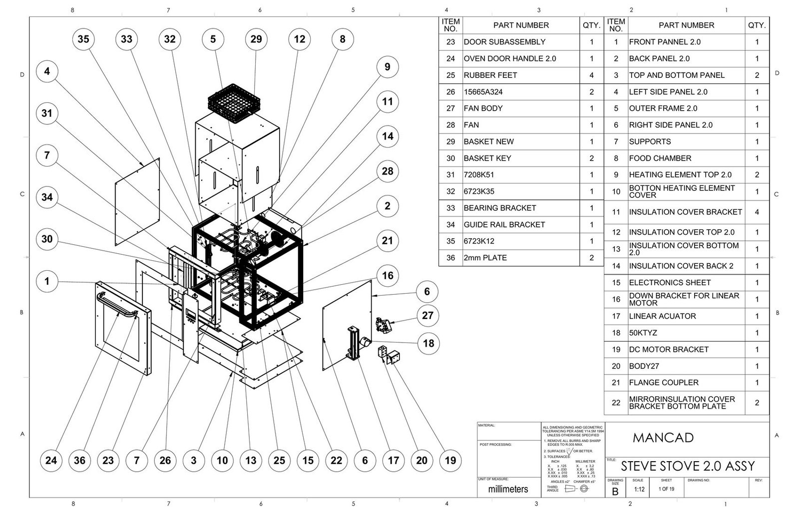
A complete 19-sheet manufacturing package for a countertop convection oven, covering a powder-coated AISI 316 front panel, insulated food chamber, top, bottom and back insulation covers, an aluminum extrusion frame and a glass-and-steel door assembly, with every part released with flat pattern development and bend data across a 36-item BOM.
View portfolioYes, bend allowances and tooling considerations are matched to the specific process and material your fabricator will actually use, not a generic default.
Both. Fabrication-ready DXF/DWG exports alongside the native 3D sheet metal model are standard for every project.
Yes, converting a solid body into a true parametric sheet metal part with correct bend lines and K-factor is a common request.
Packages have ranged from single-part drawings to full multi-part assemblies with dozens of sheet metal components and a complete BOM.
Yes, sheet metal work is frequently part of a larger mixed-material assembly rather than an isolated part.
Use these pages to compare scope and deliverables before combining services into one project.
I’ll review the available information and suggest a practical first milestone.