Step
Requirement & Reference Study
Fit, function, materials and constraints defined before any geometry is drawn.
Dimensioned manufacturing drawings and GD&T for machined, molded and sheet metal parts, prepared for real quoting and inspection, not auto-generated views with default tolerances left in place.
The service page explains the risk it solves, the deliverables included and the workflow used to reach a production-ready result.
Every stage produces a clear decision, review point or manufacturing deliverable.
Fit, function, materials and constraints defined before any geometry is drawn.
Parametric modeling reviewed early for moldability, machinability and assembly.
Full assemblies, tolerancing, and FEA/thermal validation where load or heat matter.
Dimensioned packages, flat patterns, BOMs and tolerance callouts a supplier can quote.
Prototypes confirm fit and function, then final files are packaged for production.
The portfolio example shows how the same engineering decisions appear in completed work.
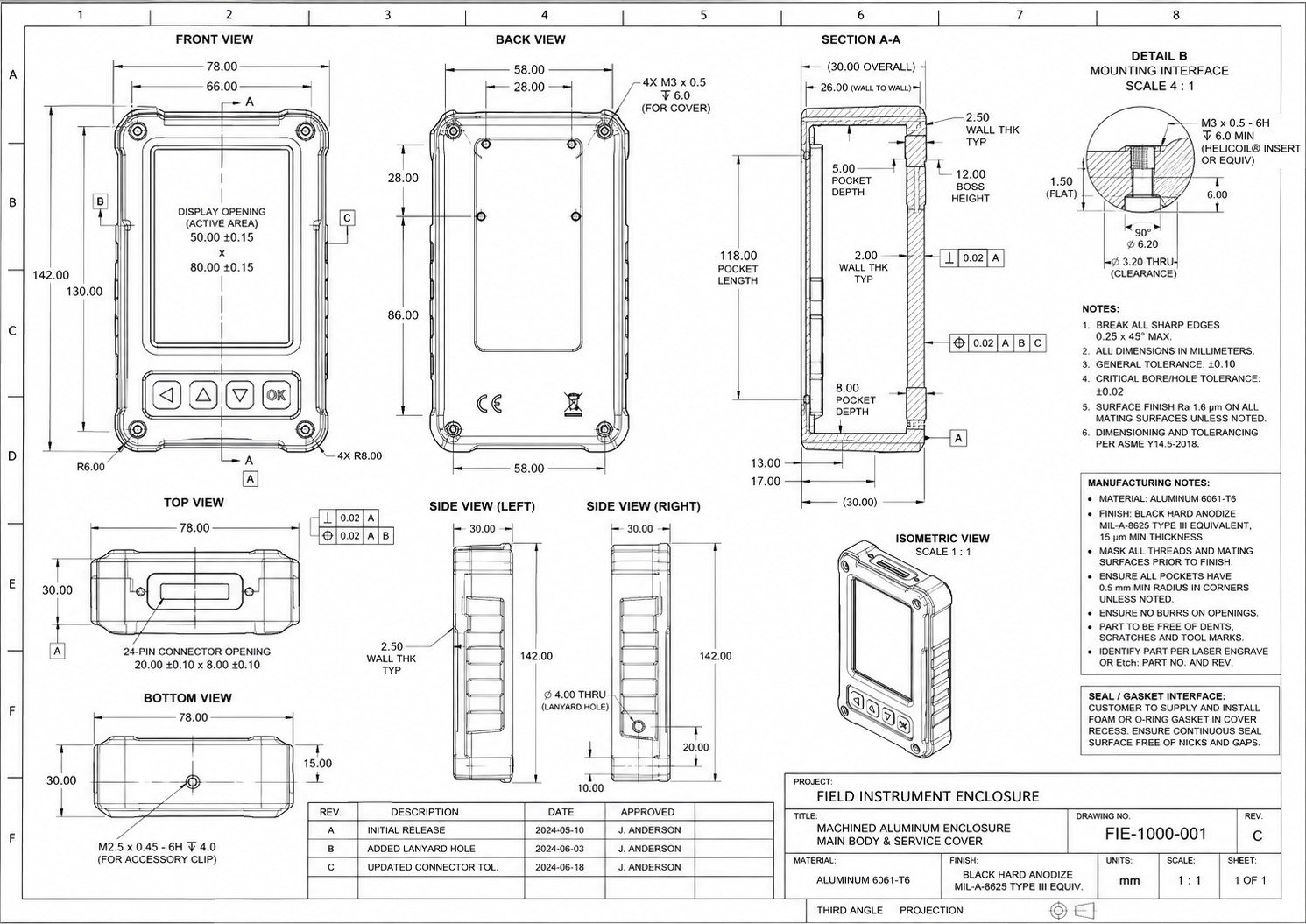
A rugged handheld instrument enclosure machined from aluminum 6061 T6 with a 50×80 mm active display opening and Helicoil-reinforced mounting bosses, where pocket depths, wall thickness and bore tolerances were defined to a critical tolerance target of ±0.02 mm.
View portfolioProper GD&T (ASME Y14.5) is applied where it matters, on critical-to-function features, rather than as a blanket default across an entire part.
Yes, working from an existing CAD model to produce a proper manufacturing drawing package is a common standalone request.
ASME Y14.5M is the standard reference, with tolerances set based on the actual mating requirements and manufacturing process rather than a copied default.
Yes, a BOM matched to the drawing revision is included for any multi-part assembly.
Yes, that is a common use case, a drawing package accurate enough to get a real quote before any tooling spend is authorized.
Use these pages to compare scope and deliverables before combining services into one project.
I’ll review the available information and suggest a practical first milestone.