Step
Requirement & Reference Study
Fit, function, materials and constraints defined before any geometry is drawn.
Structural and thermal finite element analysis for enclosures, brackets, actuators and load-bearing assemblies, used to validate a design decision before it is committed to tooling or machining.
The service page explains the risk it solves, the deliverables included and the workflow used to reach a production-ready result.
Every stage produces a clear decision, review point or manufacturing deliverable.
Fit, function, materials and constraints defined before any geometry is drawn.
Parametric modeling reviewed early for moldability, machinability and assembly.
Full assemblies, tolerancing, and FEA/thermal validation where load or heat matter.
Dimensioned packages, flat patterns, BOMs and tolerance callouts a supplier can quote.
Prototypes confirm fit and function, then final files are packaged for production.
The portfolio example shows how the same engineering decisions appear in completed work.
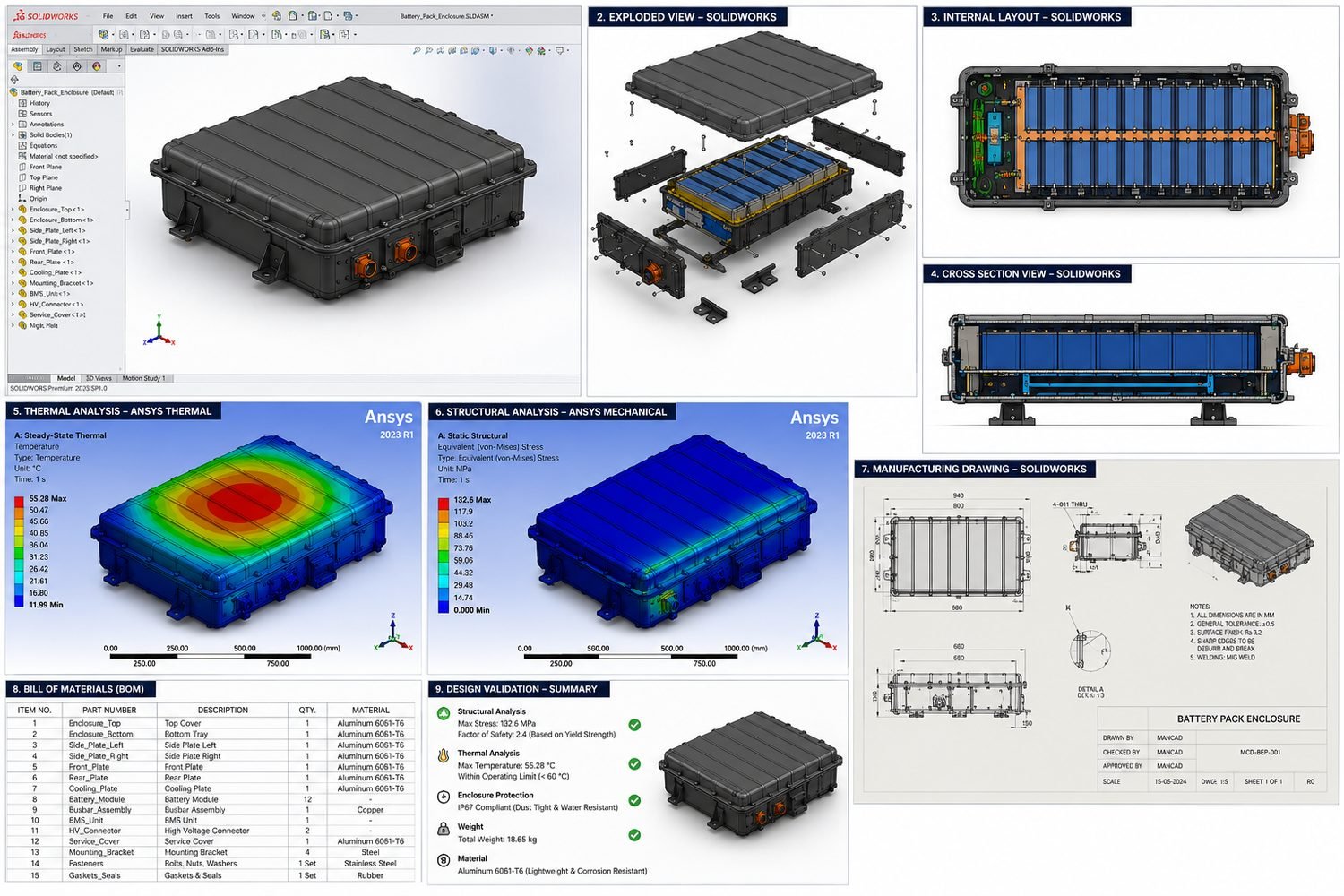
An EV battery pack enclosure machined from 6061 T6 aluminum, where Ansys Thermal and Ansys Mechanical studies indicated a 55.3°C peak temperature and a 132.6 MPa peak stress, both inside spec, validating a structural Factor of Safety of 2.4 before the manufacturing drawing was released.
View portfolioBoth, depending on the project. SolidWorks Simulation covers most structural and thermal validation; Ansys is used where a higher-fidelity study is warranted.
Yes, running FEA on an existing model, including cleaning up geometry so it meshes properly, is a common standalone request.
Load cases are defined from the product's actual use conditions wherever possible, not generic assumptions, and any assumption made is stated clearly in the results.
A written summary tied to a clear pass/fail against a target Factor of Safety or temperature limit, alongside the stress/thermal plots themselves, not just colorful images with no conclusion.
Yes, that is one of the most common and valuable uses of FEA, catching an undersized section or a stress concentration before it becomes an expensive mistake in metal.
Use these pages to compare scope and deliverables before combining services into one project.
I’ll review the available information and suggest a practical first milestone.